
Concept explainers
(a)
Find the amplitude of the motion
(a)
Answer to Problem 19.110P
The amplitude of the motion
Explanation of Solution
Given information:
The weight of the bob
The weight of the collar
The length of the simple pendulum (l) is
The amplitude of the collar
The magnitude of static deflection
The frequency
The acceleration due to gravity (g) is
Calculation:
Calculate the mass of the bob
Substitute
Calculate the mass of the collar
Substitute
Calculate the frequency of the period
Substitute
Show the system at before and after moving the collar horizontally as in Figure 1.
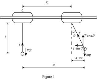
Refer Figure (1),
Before giving horizontal movement, the force mg is equal to the tension in the pendulum.
The expression for the force balance equation for initial condition as follows:
Calculate the value of
The expression for the force balance equation in x-direction in the displaced condition as follows:
Here,
The only force in the x-direction is the tension component
Substitute
Calculate the differential equation of motion using the formula:
Substitute mg for T and
Substitute
Here,
Compare the differential equation (2) with the general differential equation of motion for forced vibration
Calculate the natural circular frequency of vibration
Substitute
Calculate the amplitude of the forced vibration
Substitute
Therefore, the amplitude of the motion
(b)
Find the force that must be applied to collar C (F) to maintain the motion.
(b)
Answer to Problem 19.110P
The force that must be applied to collar C (F) to maintain the motion is
Explanation of Solution
Given information:
The weight of the bob
The weight of the collar
The length of the simple pendulum (l) is
The amplitude of the collar
The magnitude of static deflection
The frequency
The acceleration due to gravity (g) is
Calculation:
Consider the collar as a free body and show the free body diagram equation as in Figure (2).
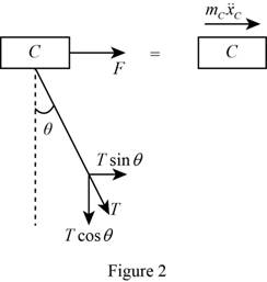
Refer Figure (2), F is the force applied to the collar to maintain the motion is F and
The expression for the force balance equation from Figure 2 as follows:
Substitute mg for T and
Substitute
The expression for the relation for
Differentiate the relation for
Substitute
Substitute
Therefore, the force that must be applied to collar C (F) to maintain the motion is
Want to see more full solutions like this?
Chapter 19 Solutions
Loose Leaf for Vector Mechanics for Engineers: Statics and Dynamics


- Question 22: The superheated steam powers a steam turbine for the production of electrical power. The steam expands in the turbine and at an intermediate expansion pressure (0.1 MPa) a fraction is extracted for a regeneration process in a surface regenerator. The turbine has an efficiency of 90%. It is requested: Define the Power Plant Schematic Analyze the steam power system considering the steam generator system in the attached figure Determine the electrical power generated and the thermal efficiency of the plant Perform an analysis on the power generated and thermal efficiency considering a variation in the steam fractions removed for regeneration ##Data: The steam generator uses biomass from coconut shells to produce 4.5 tons/h of superheated steam; The feedwater returns to the condenser at a temperature of 45°C (point A); Monitoring of the operating conditions in the steam generator indicates that the products of combustion leave the system (point B) at a temperature of 500°C;…arrow_forwardThis is an old practice exam question.arrow_forwardSteam enters the high-pressure turbine of a steam power plant that operates on the ideal reheat Rankine cycle at 700 psia and 900°F and leaves as saturated vapor. Steam is then reheated to 800°F before it expands to a pressure of 1 psia. Heat is transferred to the steam in the boiler at a rate of 6 × 10⁴ Btu/s. Steam is cooled in the condenser by the cooling water from a nearby river, which enters the condenser at 45°F. Use steam tables. NOTE: This is a multi-part question. Once an answer is submitted, you will be unable to return to this part. Determine the pressure at which reheating takes place. Use steam tables. Find: The reheat pressure is psia. (P4)Find thermal efficiencyFind m dotarrow_forward
- Air at T1 = 24°C, p1 = 1 bar, 50% relative humidity enters an insulated chamber operating at steady state with a mass flow rate of 3 kg/min and mixes with a saturated moist air stream entering at T2 = 7°C, p2 = 1 bar. A single mixed stream exits at T3 = 17°C, p3 = 1 bar. Neglect kinetic and potential energy effects Determine mass flow rate of the moist air entering at state 2, in kg/min Determine the relative humidity of the exiting stream. Determine the rate of entropy production, in kJ/min.Karrow_forwardAir at T1 = 24°C, p1 = 1 bar, 50% relative humidity enters an insulated chamber operating at steady state with a mass flow rate of 3 kg/min and mixes with a saturated moist air stream entering at T2 = 7°C, p2 = 1 bar. A single mixed stream exits at T3 = 17°C, p3 = 1 bar. Neglect kinetic and potential energy effects Determine mass flow rate of the moist air entering at state 2, in kg/min Determine the relative humidity of the exiting stream. Determine the rate of entropy production, in kJ/min.Karrow_forwardAir at T1 = 24°C, p1 = 1 bar, 50% relative humidity enters an insulated chamber operating at steady state with a mass flow rate of 3 kg/min and mixes with a saturated moist air stream entering at T2 = 7°C, p2 = 1 bar. A single mixed stream exits at T3 = 17°C, p3 = 1 bar. Neglect kinetic and potential energy effects (a) Determine mass flow rate of the moist air entering at state 2, in kg/min (b) Determine the relative humidity of the exiting stream. (c) Determine the rate of entropy production, in kJ/min.Karrow_forward
- A simple ideal Brayton cycle operates with air with minimum and maximum temperatures of 27°C and 727°C. It is designed so that the maximum cycle pressure is 2000 kPa and the minimum cycle pressure is 100 kPa. The isentropic efficiencies of the turbine and compressor are 91% and 80%, respectively, and there is a 50 kPa pressure drop across the combustion chamber. Determine the net work produced per unit mass of air each time this cycle is executed and the cycle’s thermal efficiency. Use constant specific heats at room temperature. The properties of air at room temperature are cp = 1.005 kJ/kg·K and k = 1.4. The fluid flow through the cycle is in a clockwise direction from point 1 to 4. Heat Q sub in is given to a component between points 2 and 3 of the cycle. Heat Q sub out is given out by a component between points 1 and 4. An arrow from the turbine labeled as W sub net points to the right. The net work produced per unit mass of air is kJ/kg. The thermal efficiency is %.arrow_forwardSteam enters the high-pressure turbine of a steam power plant that operates on the ideal reheat Rankine cycle at 700 psia and 900°F and leaves as saturated vapor. Steam is then reheated to 800°F before it expands to a pressure of 1 psia. Heat is transferred to the steam in the boiler at a rate of 6 × 10⁴ Btu/s. Steam is cooled in the condenser by the cooling water from a nearby river, which enters the condenser at 45°F. Use steam tables. NOTE: This is a multi-part question. Once an answer is submitted, you will be unable to return to this part. Determine the pressure at which reheating takes place. Use steam tables. The reheat pressure is psia.Find thermal efficieny Find m dotarrow_forwardThis is an old exam practice question.arrow_forward
- As shown in the figure below, moist air at T₁ = 36°C, 1 bar, and 35% relative humidity enters a heat exchanger operating at steady state with a volumetric flow rate of 10 m³/min and is cooled at constant pressure to 22°C. Ignoring kinetic and potential energy effects, determine: (a) the dew point temperature at the inlet, in °C. (b) the mass flow rate of moist air at the exit, in kg/min. (c) the relative humidity at the exit. (d) the rate of heat transfer from the moist air stream, in kW. (AV)1, T1 P₁ = 1 bar 11 = 35% 120 T₂=22°C P2 = 1 bararrow_forwardAir at T₁-24°C, p₁-1 bar, 50% relative humidity enters an insulated chamber operating at steady state with a mass flow rate of 3 kg/min and mixes with a saturated moist air stream entering at T₂-7°C, p2-1 bar. A single mixed stream exits at T3-17°C, p3-1 bar. Neglect kinetic and potential energy effects Step 1 Your answer is correct. Determine mass flow rate of the moist air entering at state 2, in kg/min. m2 = 2.1 Hint kg/min Using multiple attempts will impact your score. 5% score reduction after attempt 2 Step 2 Determine the relative humidity of the exiting stream. Փ3 = i % Attempts: 1 of 3 usedarrow_forwardA reservoir at 300 ft elevation has a 6-in.-diameter discharge pipe located 50 ft below the surface. The pipe is 600 ft long and drops in elevation to 150 ft where the flow discharges to the atmosphere. The pipe is made of riveted steel with a roughness height of 0.005 ft. Determine the flow rate without a head loss Determine the flow rate with the pipe friction head loss. (hints: Since the velocity is not known for part b and the Reynolds number and friction factor depend on velocity, you will need to iterate to find the solution. A good first guess is the velocity from part (a))arrow_forward
 Elements Of ElectromagneticsMechanical EngineeringISBN:9780190698614Author:Sadiku, Matthew N. O.Publisher:Oxford University Press
 Mechanics of Materials (10th Edition)Mechanical EngineeringISBN:9780134319650Author:Russell C. HibbelerPublisher:PEARSON
 Thermodynamics: An Engineering ApproachMechanical EngineeringISBN:9781259822674Author:Yunus A. Cengel Dr., Michael A. BolesPublisher:McGraw-Hill Education
 Control Systems EngineeringMechanical EngineeringISBN:9781118170519Author:Norman S. NisePublisher:WILEY
 Mechanics of Materials (MindTap Course List)Mechanical EngineeringISBN:9781337093347Author:Barry J. Goodno, James M. GerePublisher:Cengage Learning
 Engineering Mechanics: StaticsMechanical EngineeringISBN:9781118807330Author:James L. Meriam, L. G. Kraige, J. N. BoltonPublisher:WILEY