
MindTap Engineering, 1 term (6 months) Printed Access Card for Das/Sivakugan’s Principles of Foundation Engineering, 9th
9th Edition
ISBN: 9781337705202
Author: Das, Braja M., SIVAKUGAN, Nagaratnam
Publisher: Cengage Learning
expand_more
expand_more
format_list_bulleted
Concept explainers
Videos
Textbook Question
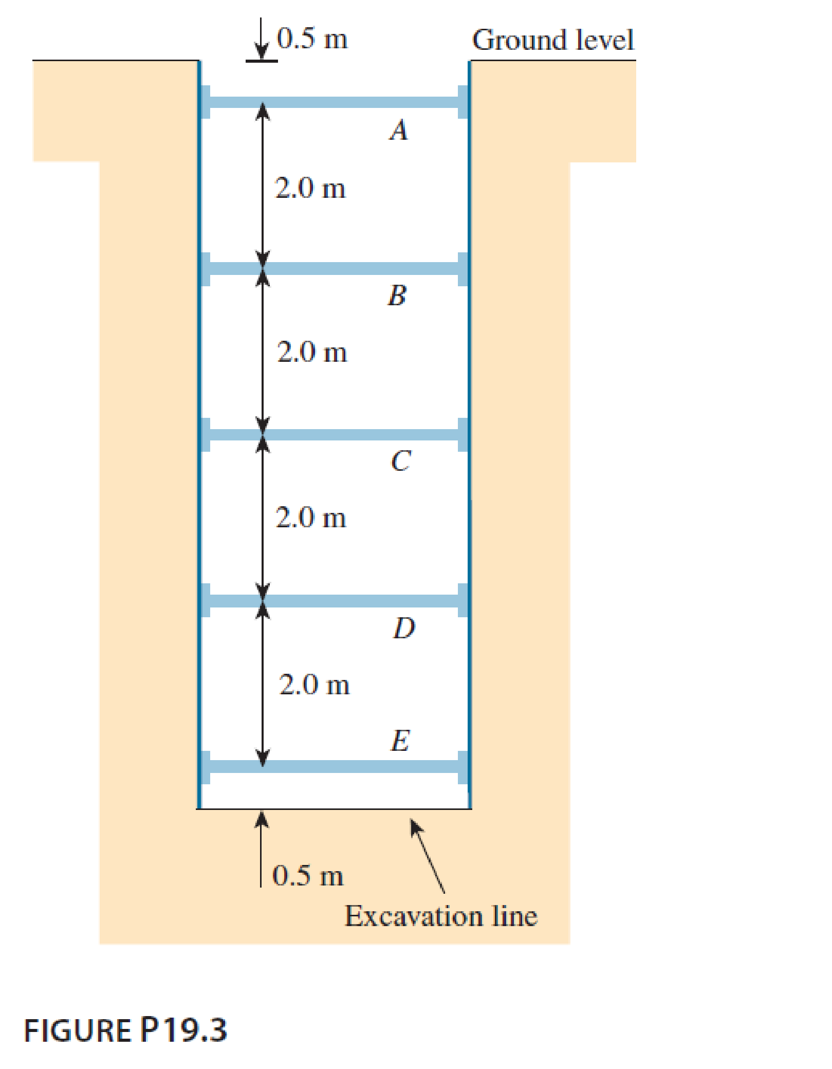
Chapter 19, Problem 19.3P
A braced cut shown in Figure P19.3 is to be made to a depth of 9.0 m in a saturated clay deposit where the unit weight is 17.65 kN/m3 and the undrained shear strength is 30 kN/m2. The struts are spaced horizontally at 3.0 m center to center. Find the strut loads.
Expert Solution & Answer

Trending nowThis is a popular solution!

Students have asked these similar questions
REINFORCED CONCRETE DESIGNANALYSIS OF SINGLY REINFORCED BEAMS (STRENGTH DESIGN METHOD)Direction:Solution must be completeUse ballpen/inkpenAnswer in two decimal placesBox your final answer
E. Estimate the required air flow rate for the new activated sludge plant at Camp Verde Problems 23-3 —
23-823-11, and 23-14 B). Use the following assumptions in preparing the estimate:
Clean water correction, a 0.70
. Salinity correction, ẞ= 0.95
. Fouling factor = 0.8
Summer wastewater temperature 22°C
• Atmospheric pressure 101.325 kPa
.Elevation 2,135 m
Depth of aerator = 4.5 m
Operating DO = 2.0 mg/L
Percent oxygen leaving aeration tank - 19%
Manufacturer's SOTR = 650 kg/d
• Manufacturer's air flow rate at standard conditions 20 m3/d aerator
23-3. The town of Camp Verde has been directed to upgrade its primary WWTP to a secondary plant
that can meet an effluent standard of 25.0 mg/L BOD5 and 30 mg/L suspended solids. They have se-
lected a completely mixed activated sludge system for the upgrade. The existing primary treatment
plant has a flow rate of 2,506 m³/d. The effluent from the primary tank has a BOD5 of 240 mg/L. Using
the following assumptions, estimate the required…
Only expert should attempt,I don't need AI solutions, because it's always incorrect please
Chapter 19 Solutions
MindTap Engineering, 1 term (6 months) Printed Access Card for Das/Sivakugan’s Principles of Foundation Engineering, 9th
Knowledge Booster


Learn more about
Need a deep-dive on the concept behind this application? Look no further. Learn more about this topic, civil-engineering and related others by exploring similar questions and additional content below.Similar questions
- The single degree of freedom (SDOF) system that you studied under free vibration in Assignment #3 - Laboratory Component has been subjected to a strong ground motion. The acceleration at the base (excitation) and the acceleration at the roof (response) of the SDOF system was recorded with sampling rate 50 Hz (50 samples per second, or dt= 0.02 seconds). The file ElCentro.txt includes the two columns of acceleration data. The first column lists the acceleration at the base of the SDOF system. The second column lists the acceleration at the roof of the SDOF system. (a) Plot the time histories of the recorded accelerations at the base and at the roof of the SDOF system. (b) Compute the acceleration, velocity and displacement time histories of the roof of the SDOF system subjected to the recorded base acceleration using the Central Difference method. Plot the accel- eration, velocity and displacement time histories. Plot the restoring force, the damping force, and the inertia force time…arrow_forwardUsing the method of virtual work, for the truss shown below, determine the horizontal displacement of joint A. Take A = 180 mm2 and E = 200 GPa for each member.arrow_forwardA gravity retaining wall is shown in the figure below. Calculate the factor of safety with respect to overturning and sliding, given the following data: Wall dimensions: H = 6 m, x₁ = 0.6 m, x2 = 2 m, x3 = 2m, x4 0.5 m, x5 = 0.75 m, x6 = 0.8 m, D= 1.5 m Soil properties: 71 = 14 kN/m³, ₁ = 32°, 72 = 18 kN/m³, 2=22°, c₂ = 40 kN/m² Y₁ c₁ = 0 H Φί x5 x6 Use the Rankine active earth pressure in your calculation. Use Yconcrete = 23.08 kN/m³. Also, use k₁ = k₂ = 2/3 and Pp = 0 in the equation FS (sliding) (ΣV) tan(k102) + Bk2c2 + Pp Pa cos a (Enter your answers to three significant figures.) FS (overturning) FS (sliding) =arrow_forward
- For the cantilever retaining wall shown in the figure below, let the following data be given: Wall dimensions: H = 8 m, x1 = 0.4 m, x2 = 0.6 m, x3 = 1.5 m, x4 3.5 m, x5 = 0.96 m, D= 1.75 m, a = 10° Soil properties: 71 = 14.8 kN/m³, ₁ = 32°, Y₂ = 1 2 = 28°, c = 30 kN/m² 17.6 kN/m³, The value of Ka is 0.3210. For 2 = 28°: N = 25.80; N₁ = 14.72; N₁ = 16.72. c=0 H Χς Calculate the factor of safety with respect to overturning, sliding, and bearing capacity. Use Yconcrete = 21.58 kN/m³. Also, use k₁ = k₂ = 2/3 and P = 0 in the equation FS (sliding) (ΣV) tan(k₁₂) + Bk2C + Pp Pa cosa (Enter your answers to three significant figures.) FS (overturning) FS (sliding) FS (bearing) =arrow_forwardQuestion 2 The following strains are obtained by a 0-60-120 strain rosette: ε0 = 300 x 10-6, 60 = 200 x 10-6 and 120= 150 x 10-6. i. Determine strains Ex, Ey and Yxy ii. Determine the strains for 0 = 40° iii. Calculate principal strains, maximum shear strain and the orientation of principal strains iv. Determine normal stresses (σx, σy) and shear stress (Txy), if E = 200kPa and v = 0.25. (Hint: You may use stress-strain relationship for plane strain, summarised in matric format as follows: E σχ бу 1-v v 0 Ex = v 1-v 0 Ey txy. (1+v)(1 − 2v) 0 0 0.5 varrow_forwardA gravity retaining wall is shown in the figure below. Calculate the factor of safety with respect to overturning and sliding, given the following data: Wall dimensions: H = 6 m, x1 = 0.6 m, x2 = 2 m, x3 = 2m, x4 0.5 m, x5 = 0.75 m, x6 = 0.8 m, D= 1.5 m Soil properties: 71 = 15.5 kN/m³, ₁ = 32°, Y2 = 18 kN/m³, 2=22°, c₂ = 40 kN/m² H x6 X2 TXT X3 Use Coulomb's active earth pressure in your calculation and let ' = 2/3 01. Use Yconcrete = 23.58 kN/m³. Also, use k₁ = k₂ = 2/3 and P = 0 in equation FS (sliding) (ΣV) tan(k₁₂2) + Bk2c + Pp Pa cos a For 1 = 32°, a = 0°, B = 71.57°, Ka = 0.45, 8' = 21.33°. (Enter your answers to three significant figures.) FS (overturning) FS (sliding) =arrow_forward
- For the cantilever retaining wall shown in the figure below, let the following data be given: Wall dimensions: H = 6.5 m, x1 = 0.3 m, x2 = 0.6 m, x3 = 0.8 m, x4 2 m, x5 = 0.8 m, D= 1.5 m, a = 0° Soil properties: 71 = 17.08 kN/m³, ₁ = 36°, Y2 = 19.65 kN/m³, 2 = 15°, c₂ = 30 kN/m² For 2=15°: N = 10.98; N₁ = 3.94; N₁ = 2.65. x2 .. c₁ = 0 Φί H x5 Calculate the factor of safety with respect to overturning, sliding, and bearing capacity. Use Yconcrete = 24.58 kN/m³. Also, use k₁ = k2 = 2/3 and P₂ = 0 in equation (EV) tan(k102) + Bk2c₂ + Pp FS (sliding) Pa cos a (Enter your answers to three significant figures.) FS (overturning) FS (sliding) FS (bearing) = = =arrow_forwardA) # of Disinfection Clearwells: 3 B) Clearwell Operation Style: Parallel (to provide contact time for disinfection using free chlorine (derived from a hypochlorite solution generated onsite). C) The facility's existing system to generate hypochlorite onsite has reached the end of its useful life, and the current operating capacity is insufficient to generate the required mass flow of hypochlorite to accommodate the future capacity of 34.5 MGD. Assume the facility plans to stop generating hypochlorite onsite and will instead purchase a bulk solution of sodium hypochlorite D) Sodium hypochlorite (NaOCI) concentration: 6.25% NaOCI by mass E) Bulk Density: 1,100 kg/m^3 F) Clearwell T10/DT Ratio: (CW1 0.43). (CW2 = 0.51), (CW3 = 0.58) DT is the theoretical mean hydraulic retention time (V/Q) G) pH: 7.0 H) Design Temperature: 15°C 1) 50% of Chlorine is lost in each clearwell J) If the concentration going into the clearwell is C, then you can assume that the concentration leaving the…arrow_forwardPlease explain step by step, and show formulaarrow_forward
- Note: Please deliver a clear, step-by-step simplified handwritten solution (without any explanations) that is entirely manually produced without AI assistance. I expect an expert-level answer, and I will evaluate and rate it based on the quality and accuracy of the work, using the provided image for additional reference. Ensure every detail is thoroughly checked for correctness before submission.arrow_forwardPlease don't explain it. But draw it out for me kindly. And appreciate your time!. All the info is in the images. Thanks!.arrow_forwardDesign a simply supported one-way pavement slab for a factored applied moment, Mu = 10 ft-kip. Use f c’ = 5,000 psi and f y = 60,000 psi. The slab is in permanent contact with soil.Hint:• Estimate a minimum slab thickness for deflection control.• Solve for the slab steel based on cover for soil contactarrow_forward
arrow_back_ios
SEE MORE QUESTIONS
arrow_forward_ios
Recommended textbooks for you
 Principles of Foundation Engineering (MindTap Cou...Civil EngineeringISBN:9781337705028Author:Braja M. Das, Nagaratnam SivakuganPublisher:Cengage Learning
 Principles of Geotechnical Engineering (MindTap C...Civil EngineeringISBN:9781305970939Author:Braja M. Das, Khaled SobhanPublisher:Cengage Learning
 Fundamentals of Geotechnical Engineering (MindTap...Civil EngineeringISBN:9781305635180Author:Braja M. Das, Nagaratnam SivakuganPublisher:Cengage Learning
 Principles of Foundation Engineering (MindTap Cou...Civil EngineeringISBN:9781305081550Author:Braja M. DasPublisher:Cengage Learning
Principles of Foundation Engineering (MindTap Cou...
Civil Engineering
ISBN:9781337705028
Author:Braja M. Das, Nagaratnam Sivakugan
Publisher:Cengage Learning
Principles of Geotechnical Engineering (MindTap C...
Civil Engineering
ISBN:9781305970939
Author:Braja M. Das, Khaled Sobhan
Publisher:Cengage Learning
Fundamentals of Geotechnical Engineering (MindTap...
Civil Engineering
ISBN:9781305635180
Author:Braja M. Das, Nagaratnam Sivakugan
Publisher:Cengage Learning
Principles of Foundation Engineering (MindTap Cou...
Civil Engineering
ISBN:9781305081550
Author:Braja M. Das
Publisher:Cengage Learning
How to build angle braces; Author: Country Living With The Harnish's;https://www.youtube.com/watch?v=3cKselS6rxY;License: Standard Youtube License