
Concept explainers
Videos
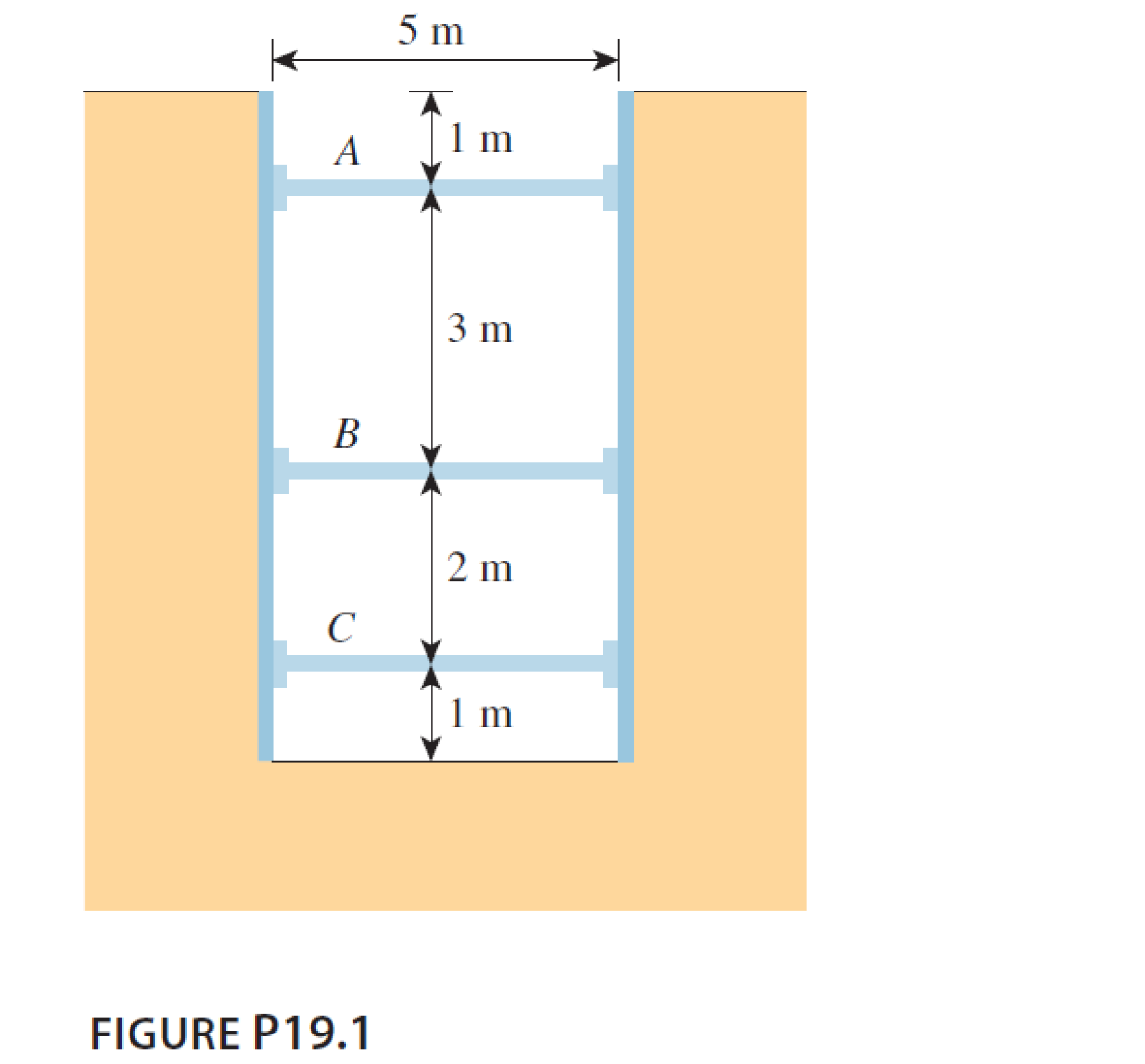
A 5 m wide braced excavation is made in a saturated clay, as shown in Figure P19.1, with the following properties: c = 20 kN/m2, ϕ = 0, and γ = 18.5 kN/m3. The struts are spaced at 5 m center to center in plan.
- a. Determine the strut forces.
- b. Determine the section modulus of the sheet pile required, assuming σall = 170 MN/m2.
- c. Determine the maximum moment for the wales at levels B and C.
a.
Find the strut force.
Answer to Problem 19.1P
The strut load at A, B, C is
Explanation of Solution
Given information:
The width of excavation is 5 m.
The height of excavation cut H is 7 m.
The unit weight of saturated clay
The coefficient of internal friction
The cohesion (c) is
The center to center spacing of strut s is 5 m.
Calculation:
Check the condition for soft to medium clay as follows:
Hence, the clay is considered as soft to medium clay.
Find the maximum lateral pressure using the formula.
The maximum lateral pressure is
Step-1:
Indicate the struts are labeled as A, B, and C and its carrying load as
Draw the pressure diagram as shown in Figure.
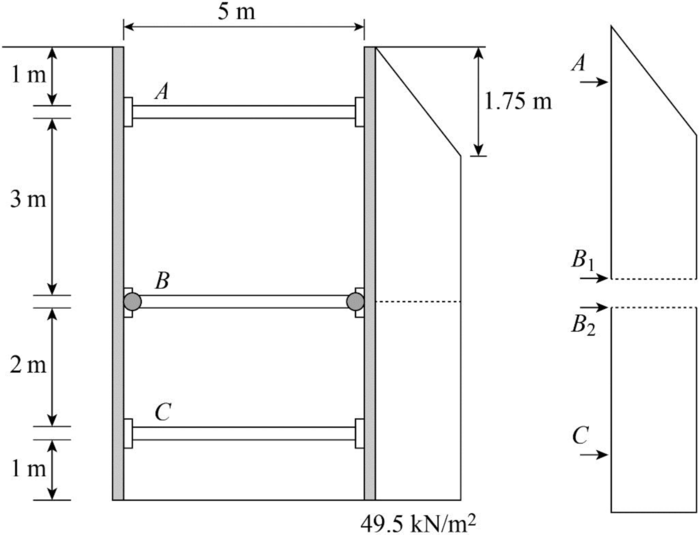
The strut sheet pile connection at B is assumed to be hinge.
Find the strut load per meter width of excavation as follows:
At the top block,
For the bottom block,
Find the strut force at A
Find the strut load at B
Find the strut load at C
Therefore, The strut load at A, B, C is
b.
Find the required section modulus for sheet pile section.
Answer to Problem 19.1P
The section modulus is
Explanation of Solution
Given information:
The allowable pressure
Calculation:
For top block,
Consider the maximum moment occurs at distance
Find the maximum moment as follows:
The maximum moment occurs at C in the lower block
Find the maximum moment at lower block as follows:
Consider that the higher value of maximum moment is
Find the required section modulus using the formula:
Refer Table 18.1, “Properties of some commercially available sheet-pile section” in the textbook.
Take the section designation as PZ-22 according to the values.
Therefore, the section modulus is
c.
Find the maximum moment for the two wales.
Answer to Problem 19.1P
The maximum moment for the wall at B is
The maximum moment for the wall at C is
Explanation of Solution
Find the maximum moment for the wall at B,
Find the maximum moment for the wall at C,
The maximum moment for the wall at B is
The maximum moment for the wall at C is
Want to see more full solutions like this?
Chapter 19 Solutions
MindTap Engineering, 1 term (6 months) Printed Access Card for Das/Sivakugan’s Principles of Foundation Engineering, 9th


- Determine the smallest value of yield stress Fy, for which a W-, M-, or S-shape from the list below will become slender. bf/2tfh/tw Shape W12 × 72 8.99 22.6 W12 × 26 8.54 47.2 M4 × 6 11.9 22.0 M12 x 11.8 6.81 62.5 M6 × 4.4 5.39 47.0 S24 × 80 4.02 41.4 S10 × 35 5.03 13.4 (Express your answer to three significant figures.) Fy = ksi To which shape does this value apply? -Select- ✓arrow_forwardCompute the nominal shear strength of an M12 × 11.8 of A572 Grade 60 steel (Fy = 60 ksi). For M12 x 11.8: d = 12 in., tw = 0.177 in., h/tw = 62.5. Vn = kipsarrow_forwardA flexural member is fabricated from two flange plates 1/2 × 71/2 and a web plate 3/8 × 19. The yield stress of the steel is 50 ksi. a. Compute the plastic section modulus Z and the plastic moment Mp with respect to the major principal axis. (Express your answers to three significant figures.) Z = Mp = in. 3 ft-kips b. Compute the elastic section modulus S and the yield moment My with respect to the major principal axis. (Express your answers to three significant figures.) S = My = in.3 ft-kipsarrow_forward
- = 65 ksi. A W16×36 of A992 steel has two holes in each flange for 7/8-inch-diameter bolts. For A992 steel: Fy = 50 ksi, Fu For a W16×36: bƒ = 6.99 in., tƒ = 0.430 in., Z = 64.0 in.³ and Sx = 56.5 in.³ a. Assuming continuous lateral support, verify that the holes must be accounted for and determine the nominal flexural strength. (Express your answer to three significant figures.) Mn = ft-kips b. What is the percent reduction in strength? (Express your answer to three significant figures.) Reduction = %arrow_forwardFind the reinforcements for the mid span and supports for an interior 9 in. thick slab (S-2) in thefloor from Problem 1. Ignore the beams and assume that the slab is supported by columns only (i.e.a flat plate). Sketch the slab and show the reinforcements including the shrinkage andtemperature reinforcement steel. Use f c’ = 4,000 psi and f y = 60,000 psi.NOTE: Problem 3 requires additional column placements at locations such as C and D. The stripof slab between these two columns will behave as a beam support to the one-way slab (with 10 ft.span). Problem 1. The figures below shows the framing plan and section of a reinforced concrete floor system.Floor beams are shown as dotted lines. The weight of the ceiling and floor finishing is 6 psf,that of the mechanical and electrical systems is 7 psf, and the weight of the partitions is 180psf. The floor live load is 105 psf. The 7 in. thick slab exterior bay (S-1) is reinforced with #5rebars @ 10 in. o.c. as the main positive…arrow_forward1- A study of freeway flow at a particular site has resulted in a calibrated speed-density relationship, as follows u = 57.5(10.008k) a) Find the free-flow speed and jam density b) Derive the equations describing flow versus speed and flow versus density c) Determine the capacity of the road 2- A rural freeway has a demand volume of 6750 v/hr. It has four 3.4 m lanes in each direction. The traffic stream is comprised of 8% heavy vehicles and a PHF of 0.94. The terrain is rolling throughout the segment. What is the level of service for the facility? What is the capacity? 3- For an urban freeway, how many 3.6 m lanes in each direction are needed to achieve LOS C on a freeway with a peak hour traffic volume of 5725 v/hr and with a PHF = 0.967 The traffic stream is comprised of 11% heavy vehicles and the location is level terrain.arrow_forward
- Note: Provide a clear, step-by-step simplified handwritten solution (with no extra explanations) that is entirely produced by hand without any AI help. I require an expert-level answer, and I will assess it based on the quality and accuracy of the work, referring to the attached image for additional guidance. Make sure every detail is carefully verified for correctness before you submit. Thanks!.arrow_forwardExample 3 Design a rectangular reinforced concrete beam having a 6 m simple span. A service dead load of 25 kN/m (not including the beam weight) and a service live load 10kn/m are to be supported. use f'c = 25 MPa and fy = 420MPaarrow_forwardNote:arrow_forward
- Note:arrow_forward3. Find the reinforcements for the mid span and supports for an interior 8 in. thick slab (S-2) in the floor from Problem 1. Ignore the beams and assume that the slab is supported by columns only. Sketch the slab and show the reinforcements including the shrinkage and temperature reinforcement steel. Use fc’ = 4,000 psi and fy = 60,000 psi.arrow_forwardProblem 4 (Apx Method) Determine (approximately) the force in each member of the truss. Assume the diagonals can support both tensile and compressive forces. 3 m 50 kN F 000 40 kN 000 000 000 000 000 000 E 000 000 000 000 000 B 3 m 20 kN D 000 000 000 000 C 3 m Problem 5 (Apx Method) Determine (approximately) the force in each member of the truss in problem 4. Assume the diagonals cannot support compressive forces.arrow_forward
 Principles of Foundation Engineering (MindTap Cou...Civil EngineeringISBN:9781337705028Author:Braja M. Das, Nagaratnam SivakuganPublisher:Cengage Learning
 Principles of Foundation Engineering (MindTap Cou...Civil EngineeringISBN:9781305081550Author:Braja M. DasPublisher:Cengage Learning
 Principles of Geotechnical Engineering (MindTap C...Civil EngineeringISBN:9781305970939Author:Braja M. Das, Khaled SobhanPublisher:Cengage Learning
 Fundamentals of Geotechnical Engineering (MindTap...Civil EngineeringISBN:9781305635180Author:Braja M. Das, Nagaratnam SivakuganPublisher:Cengage Learning