Concept explainers
Videos
You are programming the control system for a robot tractor that will be used to plant and till circular fields. (Circular fields are very common in the arid western United States, where they commonly use center-pivot irrigation, inherently giving a circular field.) To avoid having the tractor run over crops traveling directly from the outside to the center or vice versa, it will be programmed to do one double-wide spiral inward, followed by a second outward spiral exactly halfway between the lines of the inward spiral to give the desired spacing. See diagram, inward in black, outward in red (or vice versa).
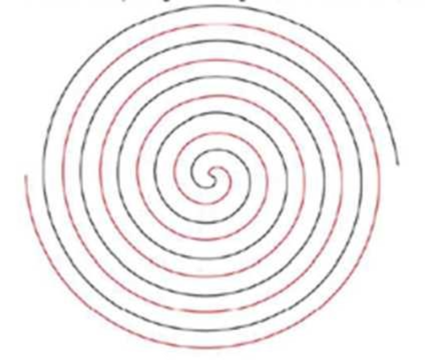
Write a program to generate this spiral pattern in a figure window.
- First, ask the user how many turns they wish for one arm of the spiral to have. In the example shown the user entered 5, for a total of 10 turns, 5 inward and 5 outward.
- All turns should be evenly spaced as shown. You may assume any outside diameter that is convenient, and the values do not need to be marked on the axes.
- You can consider either spiral to be the starting (inward) spiral as long as you end up with the correct pattern.
Hint: Recall the math of polar to rectangular conversions:
- X = R*cos(A)
- Y = R*sin(A)
Hint: Make the radius (distance from center) dependent on the total angle through which the tractor has traveled.
Want to see the full answer?
Check out a sample textbook solution
Chapter 19 Solutions
Thinking Like an Engineer: An Active Learning Approach (4th Edition)


- A piston-cylinder device initially contains 0.4 kg of nitrogen gas at 160 kPa and 140°C. Nitrogen is now expanded isothermally to a pressure of 80 kPa. Determine the boundary work done during this process. The properties of nitrogen are R= 0.2968 kJ/kg-K and k= 1.4. N₂ 160 kPa 140°C The boundary work done during this process is KJ.arrow_forward! Required information An abrasive cutoff wheel has a diameter of 5 in, is 1/16 in thick, and has a 3/4-in bore. The wheel weighs 4.80 oz and runs at 11,700 rev/min. The wheel material is isotropic, with a Poisson's ratio of 0.20, and has an ultimate strength of 12 kpsi. Choose the correct equation from the following options: Multiple Choice о σmax= (314) (4r2 — r²) - о σmax = p² (3+) (4r² + r²) 16 σmax = (314) (4r² + r²) σmax = (314) (4² - r²)arrow_forwardI don't know how to solve thisarrow_forward
- I am not able to solve this question. Each part doesn't make sense to me.arrow_forwardExercises Find the solution of the following Differential Equations 1) y" + y = 3x² 3) "+2y+3y=27x 5) y"+y=6sin(x) 7) y"+4y+4y = 18 cosh(x) 9) (4)-5y"+4y = 10 cos(x) 11) y"+y=x²+x 13) y"-2y+y=e* 15) y+2y"-y'-2y=1-4x³ 2) y"+2y' + y = x² 4) "+y=-30 sin(4x) 6) y"+4y+3y=sin(x)+2 cos(x) 8) y"-2y+2y= 2e* cos(x) 10) y+y-2y=3e* 12) y"-y=e* 14) y"+y+y=x+4x³ +12x² 16) y"-2y+2y=2e* cos(x)arrow_forwardQu. 15 What are the indices for the Plane 1 drawn in the following sketch? Qu. 16 What are the Miller indices for the Plane shown in the following cubic unit cell? this is material engineering please show all workarrow_forward
 Elements Of ElectromagneticsMechanical EngineeringISBN:9780190698614Author:Sadiku, Matthew N. O.Publisher:Oxford University Press
 Mechanics of Materials (10th Edition)Mechanical EngineeringISBN:9780134319650Author:Russell C. HibbelerPublisher:PEARSON
 Thermodynamics: An Engineering ApproachMechanical EngineeringISBN:9781259822674Author:Yunus A. Cengel Dr., Michael A. BolesPublisher:McGraw-Hill Education
 Control Systems EngineeringMechanical EngineeringISBN:9781118170519Author:Norman S. NisePublisher:WILEY
 Mechanics of Materials (MindTap Course List)Mechanical EngineeringISBN:9781337093347Author:Barry J. Goodno, James M. GerePublisher:Cengage Learning
 Engineering Mechanics: StaticsMechanical EngineeringISBN:9781118807330Author:James L. Meriam, L. G. Kraige, J. N. BoltonPublisher:WILEY