Concept explainers
Videos
Repeat Problem 19-7 using two different depths of untreated aggregate bases of 6 in. and 12 in. Highway contractors in your area can furnish rates for providing and properly laying an asphalt concrete surface and untreated granular base. Assume a structural coefficient of 0.12 for the base course. If these rates are available, determine the cost for constructing the different pavement designs if the highway section is 5 miles long and the lane width is 12 ft. Which design will you select for construction?
The cost for constructing the different pavement designs.
Answer to Problem 13P
Explanation of Solution
Given information:
Following is the given information:
Equivalent single axle load, ESAL =
CBR =
Subgrade resilient modulus =
Sub-base layer coefficient =
Granular base layer coefficient =
Elastic modulus of asphalt concrete =
mi = 1, Percentage of traffic on design lane =
SN = 4, reliability level =
and design serviceability loss =
Calculation:
We have the following formula for the calculation of truck factor:
Where, ESAL i= equivalent accumulated 18,000-lb (80-kN) single-axle load for the axle category i
fd= design lane factor,
G rn= growth factor for a given growth rate r and design period n
AADT i= first-year annual average daily traffic for axle category i
N i= number of axles on each vehicle in category i
F Ei= load equivalency factor for axle category i
Calculate ESAL for passenger car
We have the following formula for the calculation of design serviceability :
Substitute the values in the required equation.
Initial serviceability index,
Terminal serviceability index,
Let's determine the resilient modulus of subgrade:
The resilient modulus of subgrade is 1500 times CBR
The value of resilient modulus is given as follows:
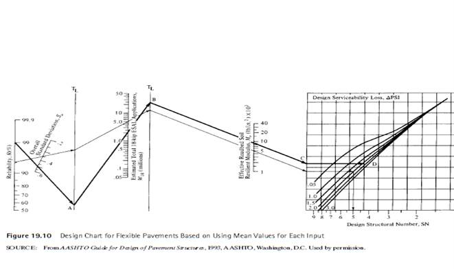
Now for the structural number, SN refer to figure 19.10
The reliability level is 90%. Starting from the point 90% in figure, extend this point to standard deviation 0.45. From standard deviation point, extend this line to line A as given in the figure.
From line A extend this line to
From ESAL extend this line to line B in the figure.
From line B extend this line to
From M rextend this line till it touches the graph. From that point, draw a horizontal line to touch the design serviceability loss, which is 2.
Extend a line vertically and take the structural number SN3reading, which is 2.5 and SN2is 2.3
Then from figure 19.6, for layer coefficient and the resilient modulus for base layer is
From figure 19.10, resilient modulus is
Refer figure 19.7 to determine layer coefficient
Now, considering the thickness aggregate base as 6 inches.
Calculate the minimum thickness.
The layer coefficient,
Substitute the values
Checking the values, we have
As the values match, thus the thickness of subgrade calculated is correct.
Calculate the required minimum thickness of base course D2is 6 inches.
Check whether the calculated thickness agrees with the calculated structural number using equation
Substituting the values, we have
Which is compatible with the structural number calculated already.
And implies that the thickness of the surface calculated is correct.
Now, the required minimum thickness of the sub-base course
By substituting the values, we have
Now, check if the calculated thickness agrees with the calculated structural number of using the following equation:
Substituting the values
Which is compatible with the structural number calculated already.
And implies that the thickness of the surface calculated is correct.
The thickness of surface 4.25 inches.
Now, considering the thickness aggregate base as 12 inches.
Calculate the minimum thickness.
Substitute the values, we have
Thus, the thickness of sub grade is 1.7 in.
Now, the thickness of the base course is given as follows:
Substitute the values.
Which is greater than 2.7, i.e., structural number.
Now, the required minimum thickness of the sub-base course
By substituting the values,
Now, check if the calculated thickness agrees with the calculated structural number of using the following equation
Substituting the values,
Which is compatible with the structural number calculated already.
And implies that the thickness of the surface calculated is correct.
Calculate construction cost for the highway considering thickness of base layer as 6 inches and 12 inches.
The cost is calculated by multiplying the measurement of road with the cost per rate.
Assume cost of surface layer as
For cost of base layer
For cost of sub-base layer
The construction cost of the highway is as follows:
Cost = L X B X t X C
For surface layer :
Substitute the values
5 miles is equal to 26400
For base layer :
Substitute the values
For sub-base layer :
Substitute the values
Now, calculate the total cost as follows:
The construction cost of the highway is as follows:
Cost = L X B X t X C
For surface layer :
Substitute the values
5 miles is equal to 26400
For base layer :
Substitute the values
For sub-base layer :
Substitute the values
Now, calculate the total cost as follows:
Conclusion:
Therefore, out of two cases the construction cost is
Want to see more full solutions like this?


- A sample of Achilles saturated with water has a mass of 1710 g. After heating in an oven, a constant mass of 1815 g is obtained. The density of solid Achilles seeds is 2.78 g/cm3. We are asked to calculate: a) The water content and void ratio b) The porosity and specific gravity of the clayey soil c) The wet density of the clayey soil, the corresponding dry density and dry densityarrow_forward8. A prestressed concrete beam is subjected to the following stress distributions: Pi is the initial prestressing force, Pe is the effective prestressing force, M, is the bending moment due to self- weight, Ma and M, are the dead load and live load bending moment, respectively. The concrete has the following properties: fr = 6000 psi and fri = 4200 psi +250 -85 -2500 +550 Pe+ Mo+Ma+Mi P alone P₁+ Mo -2450 -3500 Stress at midspan +210 +250 P, alone Pe alone -2500 -3500 Stress at ends Using Table 22.1, evaluate whether the stresses at the center of the span and the end of the span comply with the permissible stress limits. The beam is classified as U-class. Provide justifications for each condition listed in the table. Note: Calculated stresses are to be taken from the above diagram, and permissible stresses are to be calculated using Table 22.1. Compressive stresses immediately after transfer Tensile stresses immediately after transfer Compressive stresses under sustained and total…arrow_forward10. A short column is subjected to an eccentric loading. The axial load P = 1000 kips and the eccentricity e = 12 in. The material strengths are fy = 60 ksi and f = 6000 psi. The Young's modulus of steel is 29000 ksi. (a) Fill in the blanks in the interaction diagram shown below. (2pts each, 10pt total) Po Pn (1) failure range H 3" 30" Ast 6 No. 10 bars = P 22" I e H 3" (4) e = e small Load path for given e Radial lines show constant (2) eb (3) e large failure range Mn (5) e= Mo (b) Compute the balanced failure point, i.e., P and Mb.arrow_forward
- No chatgpt plsarrow_forward11. The prestressed T beam shown below is pretensioned using low relaxation stress-relieved Grade 270 strands. The steel area Aps = 2.5 in². The tensile strength is fpu = 270 ksi, and the concrete compressive strength is fr = 6000 psi. (a) Calculate the nominal moment strength Mn with hr = 6 in. 22" 15" T hf (b) Since this beam is a T-beam, the nominal moment strength M₁ increases with a thicker hf. However, M, stops increasing if he reaches a value. Determine the minimum thickness hy that can achieve the maximum nominal moment strength Mr. Also, calculate the corresponding maximum nominal moment strength Mn with the computed hf.arrow_forward10. A short column is subjected to an eccentric loading. The axial load P = 1000 kips and the eccentricity e = 12 in. The material strengths are fy = 60 ksi and f = 6000 psi. The Young's modulus of steel is 29000 ksi. (a) Fill in the blanks in the interaction diagram shown below. 30" Ast 6 No. 10 bars = Pn (1) Po (4) e = e small Load path for given e failure range Radial lines show constant (2) eb (3) e large failure range Mn (5) e= Mo (b) Compute the balanced failure point, i.e., P and Mb. H 3" P 22" I e H 3"arrow_forward
- 10. A short column is subjected to an eccentric loading. The axial load P = 1000 kips and the eccentricity e = 12 in. The material strengths are fy = 60 ksi and f = 6000 psi. The Young's modulus of steel is 29000 ksi. (a) Fill in the blanks in the interaction diagram shown below. 30" Ast 6 No. 10 bars = Pn (1) Po (4) e = e small Load path for given e failure range Radial lines show constant (2) eb (3) e large failure range Mn (5) e= Mo (b) Compute the balanced failure point, i.e., P and Mb. H 3" P 22" I e H 3"arrow_forward7. Match the given strand profiles with the corresponding loading conditions for a prestressed concrete (PSC) beam. Strand profile (b) (d) (c) (a) Ꮎ Load on a beamarrow_forward4. For serviceability considerations, the effective moment of inertia (Ie) is calculated using the following formula: le 1 - 1cr ((2/3) Mcr) Ma 2 - وا ≥ Note that the upper bound was previously set as Iut in the earlier ACI equation. (a) Arrange the following moment of inertia values in ascending order (from smallest to largest): le, Ier, Ig and lut (b) Mer is the cracking moment. Choose the cross-section that should be used to compute Mcr. NA. h 5. Identify and circle the figure that represents the scenario in which the torsional effect is permitted to be reduced according to the ACI code provisions. (3 pts) mt mi B (b)arrow_forward
- I will rate, thanksarrow_forward. 9. A reinforced concrete beam is subjected to V/ = 40 kips and Tu/ = 12 ft kips at the critical section. Given conditions: ⚫ Longitudinal reinforcements use No. 8 grade 60 steel with an effective depth d = 20 in. For shear capacity, V = 18 kips and V₂ = 22 kips • For transverse reinforcements, use No. 3 bars with grade 60. • The effective torsional area of A. = 150 in². • Crack angle = 45° ⚫ The minimum stirrup spacing is Smin = 4" and the maximum stirrup spacing is Smax = Find the required stirrup spacing at the critical section. 8".arrow_forward3. The beam shown on the right uses three No. 8 bars made of Grade 60 steel as longitudinal reinforcement. The allowable maximum center-to-center spacing of the longitudinal rebars has been determined to be 10 inches. Now assume that Grade 80 steel will be used instead. Determine whether the beam satisfies the rebar spacing requirements according to the ACI Code. Additional assumptions: • Estimate fs = fy • 20" Clear cover: ? 12" Clear side cover: 1.5" The clear cover depth cc and the clear side cover remain unchanged, regardless of the change in material.arrow_forward
 Traffic and Highway EngineeringCivil EngineeringISBN:9781305156241Author:Garber, Nicholas J.Publisher:Cengage Learning
 Construction Materials, Methods and Techniques (M...Civil EngineeringISBN:9781305086272Author:William P. Spence, Eva KultermannPublisher:Cengage Learning
 Fundamentals Of Construction EstimatingCivil EngineeringISBN:9781337399395Author:Pratt, David J.Publisher:Cengage,
 Principles of Geotechnical Engineering (MindTap C...Civil EngineeringISBN:9781305970939Author:Braja M. Das, Khaled SobhanPublisher:Cengage Learning
 Solid Waste EngineeringCivil EngineeringISBN:9781305635203Author:Worrell, William A.Publisher:Cengage Learning,