
Concept explainers
Videos
(a)
The angular velocity of the sheet metal component at time
Answer to Problem 18.78P
The angular velocity of the sheet metal component at time
Explanation of Solution
Given information:
The total mass is
Write the expression for the angular velocity of sheet metal component.
Here, the angular velocity of the sheet metal component is
Calculation:
Substitute
Conclusion:
The angular velocity of the sheet metal component at time
(b)
The dynamic reactions at
The dynamic reactions at
Answer to Problem 18.78P
The dynamic reactions at
The dynamic reactions at
Explanation of Solution
Write the expression for the sum of the moment acting on the body along x -direction.
Here, the product of the moment of the inertia of
Write the expression for the sum of the moment acting on the body along y -direction.
Write the expression for the sum of the moment acting on the body along z -direction.
Here, the moment of the inertia along the z -direction is
Draw the diagram for the for the sheet metal component.
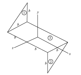
Figure-(1)
Write the expression for the area of the section 1 shown in the Figure-(1).
Here, the constant dimension is
Write the expression for the area of the section 2 shown in the Figure-(1).
Write the expression for the area of the section 3 shown in the Figure-(1).
Write the expression for the total area of the sheet.
Substitute
Write the expression of mass per unit area of the system.
Here, the mass of the sheet metal component is
Write the expression for the variation of the
Here, the coordinate of the considered point is
The below figure represent the schematic diagram of the elemental strip of section 1.
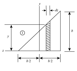
Figure-(2)
Write the expression for the distance of the centroid of the element from the
Write the expression for the mass of the elemental strip.
Here, the area of the elemental strip is
Write the expression for the moment of inertia of the element with respect to z- axis.
Write the expression for the moment of the inertia of the section 1.
Write the expression for the product of moment of inertia of the plane
Write the expression for the product of moment of inertia of the plane
Write the expression for the variation of the
The below figure represent the schematic diagram of the elemental strip of section 2.
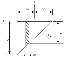
Figure-(3)
Write the expression for the mass of the elemental strip of section 2.
Write the expression for the moment of the inertia of the section 2.
Write the expression for the product of moment of inertia of the plane
Write the expression for the product of moment of inertia of the plane
Write the expression of mass per unit area of the section3 in Figure-(1).
Here, the mass of the rectangular sheet metal component is
Write the expression for the moment of the inertia of the section 3.
The product moment of the inertia for the plane
Write the expression for the moment of the inertia of the whole system.
Write the expression for the product of moment of inertia of the whole system.
Write the expression for the product of moment of inertia of the whole system.
Draw the diagram for the system to shows the action of forces on the system.
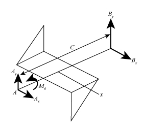
Figure-(4)
Here, the reaction on the point
Write the expression for the dynamic reaction at point
Write the expression for the dynamic reaction at point
Write the expression for the reaction forces along the y- direction.
Write the expression for the reaction forces along the x- direction.
Write the expression for the sum of the moment acting on the body along x -direction.
Here, distance between the point
Write the expression for the sum of the moment acting on the body along y -direction.
Calculation:
Substitute
Substitute
Substitute
Substitute
Substitute
Substitute
Substitute
Substitute
Substitute
Substitute
Substitute
Substitute
Substitute
Substitute
Substitute
Substitute
Substitute
Substitute
Substitute
Substitute
Substitute
Substitute
Substitute
Conclusion:
The dynamic reactions at
The dynamic reactions at
Want to see more full solutions like this?
Chapter 18 Solutions
Vector Mechanics For Engineers


- Q1/ For what value of x do the power series converge: 8 (-1)n-1. x2n-1 2n-1 x3 x5 = X n=1 3 Q2/ Find the Interval of convergence and Radius of convergence of the series: 8 n Σ 3+1 n=1 (x)"arrow_forwardExample-1: l D A uniform rotor of length 0.6 m and diameter 0.4 m is made of steel (density 7810 kg/m³) is supported by identical short bearings of stiffness 1 MN/m in the horizontal and vertical directions. If the distance between the bearings is 0.7 m, determine the natural frequencies and plot whirl speed map. Solution: Barrow_forwardfind the laplace transform for the flowing function 2(1-e) Ans. F(s)=- S 12) k 0 Ans. F(s)= k s(1+e) 0 a 2a 3a 4a 13) 2+ Ans. F(s)= 1 s(1+e") 3 14) f(t)=1, 0arrow_forwardFind the solution of the following Differential Equations Using Laplace Transforms 1) 4y+2y=0. y(0)=2. y'(0)=0. 2) y+w²y=0, (0)=A, y'(0)=B. 3) +2y-8y 0. y(0)=1. y'(0)-8. 4)-2-3y=0, y(0)=1. y'(0)=7. 5) y-ky'=0, y(0)=2, y'(0)=k. 6) y+ky'-2k²y=0, y(0)=2, y'(0) = 2k. 7) '+4y=0, y(0)=2.8 8) y+y=17 sin(21), y(0)=-1. 9) y-y-6y=0, y(0)=6, y'(0)=13. 10) y=0. y(0)=4, y' (0)=0. 11) -4y+4y-0, y(0)=2.1. y'(0)=3.9 12) y+2y'+2y=0, y(0)=1, y'(0)=-3. 13) +7y+12y=21e". y(0)=3.5. y'(0)=-10. 14) "+9y=10e". y(0)=0, y'(0)=0. 15) +3y+2.25y=91' +64. y(0)=1. y'(0) = 31.5 16) -6y+5y-29 cos(2t). y(0)=3.2, y'(0)=6.2 17) y+2y+2y=0, y(0)=0. y'(0)=1. 18) y+2y+17y=0, y(0)=0. y'(0)=12. 19) y"-4y+5y=0, y(0)=1, y'(0)=2. 20) 9y-6y+y=0, (0)-3, y'(0)=1. 21) -2y+10y=0, y(0)=3, y'(0)=3. 22) 4y-4y+37y=0, y(0)=3. y'(0)=1.5 23) 4y-8y+5y=0, y(0)=0, y'(0)=1. 24) ++1.25y-0, y(0)=1, y'(0)=-0.5 25) y 2 cos(r). y(0)=2. y'(0) = 0. 26) -4y+3y-0, y(0)=3, y(0) 7. 27) y+2y+y=e y(0)=0. y'(0)=0. 28) y+2y-3y=10sinh(27), y(0)=0. y'(0)=4. 29)…arrow_forwardAuto Controls A union feedback control system has the following open loop transfer function where k>0 is a variable proportional gain i. for K = 1 , derive the exact magnitude and phase expressions of G(jw). ii) for K = 1 , identify the gaincross-over frequency (Wgc) [where IG(jo))| 1] and phase cross-overfrequency [where <G(jw) = - 180]. You can use MATLAB command "margin" to obtain there quantities. iii) Calculate gain margin (in dB) and phase margin (in degrees) ·State whether the closed-loop is stable for K = 1 and briefly justify your answer based on the margin . (Gain marginPhase margin) iv. what happens to the gain margin and Phase margin when you increase the value of K?you You can use for loop in MATLAB to check that.Helpful matlab commands : if, bode, margin, rlocus NO COPIED SOLUTIONSarrow_forwardThe 120 kg wheel has a radius of gyration of 0.7 m. A force P with a magnitude of 50 N is applied at the edge of the wheel as seen in the diagram. The coefficient of static friction is 0.3, and the coefficient of kinetic friction is 0.25. Find the acceleration and angular acceleration of the wheel.arrow_forwardAuto Controls Using MATLAB , find the magnitude and phase plot of the compensators NO COPIED SOLUTIONSarrow_forward4-81 The corner shown in Figure P4-81 is initially uniform at 300°C and then suddenly exposed to a convection environment at 50°C with h 60 W/m². °C. Assume the = 2 solid has the properties of fireclay brick. Examine nodes 1, 2, 3, 4, and 5 and deter- mine the maximum time increment which may be used for a transient numerical calculation. Figure P4-81 1 2 3 4 1 cm 5 6 1 cm 2 cm h, T + 2 cmarrow_forwardAuto Controls A union feedback control system has the following open loop transfer function where k>0 is a variable proportional gain i. for K = 1 , derive the exact magnitude and phase expressions of G(jw). ii) for K = 1 , identify the gaincross-over frequency (Wgc) [where IG(jo))| 1] and phase cross-overfrequency [where <G(jw) = - 180]. You can use MATLAB command "margin" to obtain there quantities. iii) Calculate gain margin (in dB) and phase margin (in degrees) ·State whether the closed-loop is stable for K = 1 and briefly justify your answer based on the margin . (Gain marginPhase margin) iv. what happens to the gain margin and Phase margin when you increase the value of K?you You can use for loop in MATLAB to check that.Helpful matlab commands : if, bode, margin, rlocus NO COPIED SOLUTIONSarrow_forwardAuto Controls Hand sketch the root Focus of the following transfer function How many asymptotes are there ?what are the angles of the asymptotes?Does the system remain stable for all values of K NO COPIED SOLUTIONSarrow_forward-400" 150" in Datum 80" 90" -280"arrow_forwardUsing hand drawing both of themarrow_forwardarrow_back_iosSEE MORE QUESTIONSarrow_forward_ios
 Elements Of ElectromagneticsMechanical EngineeringISBN:9780190698614Author:Sadiku, Matthew N. O.Publisher:Oxford University Press
 Mechanics of Materials (10th Edition)Mechanical EngineeringISBN:9780134319650Author:Russell C. HibbelerPublisher:PEARSON
 Thermodynamics: An Engineering ApproachMechanical EngineeringISBN:9781259822674Author:Yunus A. Cengel Dr., Michael A. BolesPublisher:McGraw-Hill Education
 Control Systems EngineeringMechanical EngineeringISBN:9781118170519Author:Norman S. NisePublisher:WILEY
 Mechanics of Materials (MindTap Course List)Mechanical EngineeringISBN:9781337093347Author:Barry J. Goodno, James M. GerePublisher:Cengage Learning
 Engineering Mechanics: StaticsMechanical EngineeringISBN:9781118807330Author:James L. Meriam, L. G. Kraige, J. N. BoltonPublisher:WILEY