
Introductory Circuit Analysis; Laboratory Manual For Introductory Circuit Analysis Format: Kit/package/shrinkwrap
13th Edition
ISBN: 9780134297446
Author: Boylestad, Robert L.
Publisher: Prentice Hall
expand_more
expand_more
format_list_bulleted
Concept explainers
Videos
Textbook Question
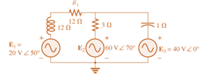
Chapter 18, Problem 7P
Write the mesh equations for the network of Fig. 18.67. Determine the current through the resistor R1.
 .
.
Expert Solution & Answer
Want to see the full answer?
Check out a sample textbook solution
Students have asked these similar questions
5) A circuit is given as shown
(a) Find currents i₁, L2 and is
.
(6) Find voltages V, V2, V3 and Vy
(c) For each circuit element in the circuit and the two sources,
state whether they are ABSORBING SUPPLYING
POWER and how much power is absorbed or supplied.
+ V₁
CIE,
1A
+2V-
C/E
AS
1A
+
-
4A
Vy+
CES
CIES
2A4
+
IOV
+-
+
+
V2
1
434
12V
GV
Determine the eigenvalues and eigenvectors of using Gauss
A =
-3
322
20
132
-3°
10
-2 4
elimination
Determine the eigenvalues and eigenvectors of
1-3 3
A =
3-53
6-64
Chapter 18 Solutions
Introductory Circuit Analysis; Laboratory Manual For Introductory Circuit Analysis Format: Kit/package/shrinkwrap
Ch. 18 - Discuss, in your own words, the difference between...Ch. 18 - Convert the voltage source in Fig. 18.62 to a...Ch. 18 - Convert the current source in Fig. 18.63 to a...Ch. 18 - Convert the votage source in Fig. 18.64(a) to a...Ch. 18 - Write the mesh equations for the network of Fig....Ch. 18 - Write the mesh equations for the network of Fig....Ch. 18 - Write the mesh equations for the network of Fig....Ch. 18 - Write the mesh equations for the network of Fig....Ch. 18 - Write the mesh equations for the network of Fig....Ch. 18 - Write the mesh equtions for the network of Fig....
Ch. 18 - Write the mesh equations for the network of Fig....Ch. 18 - Using mesh analysis, determine the current IL (in...Ch. 18 - Using mesh analysis, determine the current IL (in...Ch. 18 - Write the mesh equations for the network of Fig....Ch. 18 - Write the mesh equations for the network of...Ch. 18 - Write the mesh equations for the network of Fig....Ch. 18 - Determine the nodal voltages for the network of...Ch. 18 - Determine the nodal voltages for the network of...Ch. 18 - Determine the nodal voltages for the network of...Ch. 18 - Determine the nodal voltages for the network of...Ch. 18 - Determine the nodal voltages for the network of...Ch. 18 - Determine the nodal voltages for the network of...Ch. 18 - Determine the nodal votas for the network of Fig....Ch. 18 - Determine the nodal voltages for the network of...Ch. 18 - Write the nodal equations for the network in Fig....Ch. 18 - Write the nodal equations for the network of Fig....Ch. 18 - Write the nodal equations for the network of Fig....Ch. 18 - Write the nodal equations for the network of Fig....Ch. 18 - For the network of Fig. 18.87, determine the...Ch. 18 - For the bridge network in Fig. 18.88: Fig. 18.88...Ch. 18 - For the bridge network in Fig. 18.89: a. Is the...Ch. 18 - The Hay bridge in Fig. 18.90 is balanced. Using...Ch. 18 - Determine whether the Maxwell bridge in Fig. 18.91...Ch. 18 - Derive the balance equations (18.16) and (18.17)...Ch. 18 - Determine the balance equations for the inductance...Ch. 18 - Using the -YorY-conversion, determine the current...Ch. 18 - Using the -YorY-conversion, determine the current...Ch. 18 - Using the -YorY-conversion, determine the current...Ch. 18 - Using the -YorY-conversion, determine the current...Ch. 18 - Determine the mesh currents for the network of...Ch. 18 - Prob. 41PCh. 18 - Prob. 42PCh. 18 - Prob. 43PCh. 18 - Prob. 44PCh. 18 - Determine the nodal voltages for the network of...Ch. 18 - Determine the nodal voltages for the network of...Ch. 18 - Prob. 47PCh. 18 - Determine the nodal voltages for the network of...Ch. 18 - Determine the nodal voltages for the network of...
Additional Engineering Textbook Solutions
Find more solutions based on key concepts
How are relationships between tables expressed in a relational database?
Modern Database Management
Why is the study of database technology important?
Database Concepts (8th Edition)
Assume a telephone signal travels through a cable at two-thirds the speed of light. How long does it take the s...
Electric Circuits. (11th Edition)
This optional Google account security feature sends you a message with a code that you must enter, in addition ...
SURVEY OF OPERATING SYSTEMS
What is an uninitialized variable?
Starting Out with Programming Logic and Design (5th Edition) (What's New in Computer Science)
How does a computers main memory differ from its auxiliary memory?
Java: An Introduction to Problem Solving and Programming (8th Edition)
Knowledge Booster


Learn more about
Need a deep-dive on the concept behind this application? Look no further. Learn more about this topic, electrical-engineering and related others by exploring similar questions and additional content below.Similar questions
- Consider the following transformer circuit assuming an ideal transformer. In this circuit the signal generator will provide a 10-Volt peak-to-peak sinusoidal signal at a frequency of 1.0 kHz. Assume that L₁ = 0.65 H, L2 = 0.00492 H (=4.92 mH) and that the coupling constant = 0.99925. + VG1( R1 1k N1:N2 11.5:1 12 V1 N1 N2 V2 R2 8.2 1) Find the following using the theory presented in the prelab reading: a) Start with Equations (2) of the prelab reading and show that the input impedance to an ideal transformer is given by the equation for Z1 (=V1/11) in Equations (4) of the prelab reading. Equations (2) are: V₁ = joLI₁ + jœMI₂ and V₂ = j@MI₁ +j@L₂I₂ The equation for the input impedance is: Z₁ = 1½ = jwL₁ + (WM)² jwL₂+ZL b) Assuming that Z is a real impedance, find the equations for the real and imaginary parts of Z1. c) Use your equations from part (b) to calculate the value of the input impedance (Z) at an operating frequency of 200 Hz. Assume that the load impedance is 8.2 Ohms…arrow_forwardUse: R1 = 1.5K, R2 = 5K, R3 = 1K, R4 = 2K, R5 = 2K, R6 = 1K. 40%: Find the value for Vs (in V) such as IR2 = 1mA. 40%: Find the voltage VD. 20%: simulate the circuit in Falstad (attach the link). A 1,5k B R1 Vs L 5k P2 R2 R6 E C R3 С IR2= 1mA D H4 R4 2k 2k R5arrow_forwardThe joint pdf of random variables X=1, 2 and Y=1,2,3 is Y P(X,Y)= X [0.105 0.2 0.15] 0.151 0.18arrow_forward
- Find the eigenvalues and the corresponding eigen vectors of the following matrix: -5 A = [ 21 -7 4]arrow_forward+ 2) Acircuit is given as shown. (a) Find and label the circuit nodes (6) Determine voltages V₁, V2, V3 and Vy 4V C/E 노동 + 051 V4 + C/E + 3V- + /E5V 1 av + C E uk لا + V3C/E CIE + E6V -arrow_forwardConsider the following transformer circuit assuming an ideal transformer. In this circuit the signal generator will provide a 10-Volt peak-to-peak sinusoidal signal at a frequency of 1.0 kHz. Assume that L₁ = 0.65 H, L2 = 0.00492 H (=4.92 mH) and that the coupling constant = 0.99925. + VG1( R1 1k N1:N2 11.5:1 12 V1 N1 N2 V2 R2 8.2 1) Find the following using the theory presented in the prelab reading: a) Start with Equations (2) of the prelab reading and show that the input impedance to an ideal transformer is given by the equation for Z1 (=V1/11) in Equations (4) of the prelab reading. Equations (2) are: V₁ = joLI₁ + jœMI₂ and V₂ = j@MI₁ +j@L₂I₂ The equation for the input impedance is: Z₁ = 1½ = jwL₁ + (WM)² jwL₂+ZL b) Assuming that Z is a real impedance, find the equations for the real and imaginary parts of Z1. c) Use your equations from part (b) to calculate the value of the input impedance (Z) at an operating frequency of 200 Hz. Assume that the load impedance is 8.2 Ohms…arrow_forward
- HANDWRITTEN SOLUTION PLEASE NOT USING AIarrow_forwardFor the network of Fig. 7.93, determine: a. ID, and VGS₂- 18 V b. Vps and Vs. Shockley's equation, VGS ID= Vp) ID Vos V 1- VIDSS VGSQ VG = R₂VDD R₁ + R2 VGS VG-IDRS VDS VDD-ID(RD + Rs) (a) ID = 9 mA, VGS₁ = 0.5 V (b) VDs = 7.69 V, Vs = -0.5 V • 2.2 ΚΩ Dss = 8 mA Vp=-8V • 0.39 ΚΩ 8-4 V FIG. 7.93arrow_forwardHANDWRITTEN SOLUTION NOT USING AIarrow_forward
arrow_back_ios
SEE MORE QUESTIONS
arrow_forward_ios
Recommended textbooks for you
 Introductory Circuit Analysis (13th Edition)Electrical EngineeringISBN:9780133923605Author:Robert L. BoylestadPublisher:PEARSON
 Delmar's Standard Textbook Of ElectricityElectrical EngineeringISBN:9781337900348Author:Stephen L. HermanPublisher:Cengage Learning
 Programmable Logic ControllersElectrical EngineeringISBN:9780073373843Author:Frank D. PetruzellaPublisher:McGraw-Hill Education
 Fundamentals of Electric CircuitsElectrical EngineeringISBN:9780078028229Author:Charles K Alexander, Matthew SadikuPublisher:McGraw-Hill Education
 Electric Circuits. (11th Edition)Electrical EngineeringISBN:9780134746968Author:James W. Nilsson, Susan RiedelPublisher:PEARSON
 Engineering ElectromagneticsElectrical EngineeringISBN:9780078028151Author:Hayt, William H. (william Hart), Jr, BUCK, John A.Publisher:Mcgraw-hill Education,
Introductory Circuit Analysis (13th Edition)
Electrical Engineering
ISBN:9780133923605
Author:Robert L. Boylestad
Publisher:PEARSON
Delmar's Standard Textbook Of Electricity
Electrical Engineering
ISBN:9781337900348
Author:Stephen L. Herman
Publisher:Cengage Learning
Programmable Logic Controllers
Electrical Engineering
ISBN:9780073373843
Author:Frank D. Petruzella
Publisher:McGraw-Hill Education
Fundamentals of Electric Circuits
Electrical Engineering
ISBN:9780078028229
Author:Charles K Alexander, Matthew Sadiku
Publisher:McGraw-Hill Education
Electric Circuits. (11th Edition)
Electrical Engineering
ISBN:9780134746968
Author:James W. Nilsson, Susan Riedel
Publisher:PEARSON
Engineering Electromagnetics
Electrical Engineering
ISBN:9780078028151
Author:Hayt, William H. (william Hart), Jr, BUCK, John A.
Publisher:Mcgraw-hill Education,
Current Divider Rule; Author: Neso Academy;https://www.youtube.com/watch?v=hRU1mKWUehY;License: Standard YouTube License, CC-BY