
Electronics Fundamentals: Circuits, Devices & Applications
8th Edition
ISBN: 9780135072950
Author: Thomas L. Floyd, David Buchla
Publisher: Prentice Hall
expand_more
expand_more
format_list_bulleted
Concept explainers
Videos
Textbook Question
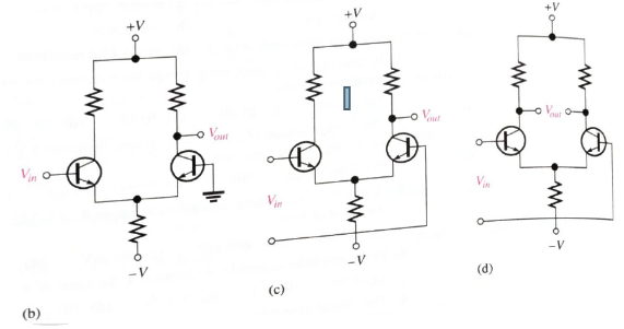
Chapter 18, Problem 3P
Identify the type of input and output configuration for each diff-amp in Figure 18-35.
Expert Solution & Answer
Want to see the full answer?
Check out a sample textbook solution
Students have asked these similar questions
I need help
The values of the circuit elements in the circuit shown in the figure are given below.The initial energies of the capacitors and the coil are zero.Accordingly, how many volts is the voltage vo at t=0.55 seconds?
vs(t) = 2cos(4000t)u(t) VR = 19 ohmL = 20 HC1 = 1/5 FC2 = 1/2 F
could you please show steps on how the answer was derived. Vo(t)=3.922 cos(1000t-71.31')V
Chapter 18 Solutions
Electronics Fundamentals: Circuits, Devices & Applications
Ch. 18 - When a diff-amp has identical signals on both...Ch. 18 - A high CMRR for a diff-amp means the common-mode...Ch. 18 - Prob. 3TFQCh. 18 - The open-loop voltage gain of an op-amp is also...Ch. 18 - Prob. 5TFQCh. 18 - Prob. 6TFQCh. 18 - In a voltage-follower, the open-loop and...Ch. 18 - Prob. 8TFQCh. 18 - Prob. 9TFQCh. 18 - If the feedback resistor in an amplifier is open,...
Ch. 18 - Which characteristic docs not necessarily apply to...Ch. 18 - In selecting an op-amp. suppose you have several...Ch. 18 - Prob. 3STCh. 18 - Prob. 4STCh. 18 - Prob. 5STCh. 18 - Prob. 6STCh. 18 - Prob. 7STCh. 18 - Prob. 8STCh. 18 - If you know an op-amp's open-loop gain and nothing...Ch. 18 - Prob. 10STCh. 18 - Prob. 11STCh. 18 - The highest possible input resistance is achieved...Ch. 18 - Compare a practical op-amp to an ideal op-amp.Ch. 18 - Two IC op-amps are available to you. Their...Ch. 18 - Identify the type of input and output...Ch. 18 - Prob. 4PCh. 18 - A certain diff-amp has a differential gain of 60...Ch. 18 - A certain diff-amp has a CMRR of 65 dB. If the...Ch. 18 - Identify the type of input mode for each op-amp in...Ch. 18 - Show the common-mode input in Figure 18-37 in an...Ch. 18 - Determine the bias current, IBIAS, given that the...Ch. 18 - Distinguish between input bias current and input...Ch. 18 - A certain op-amp has a CMRR of 250,000. Convert...Ch. 18 - The open-loop gain of a certain op-amp is 175,000....Ch. 18 - The op-amp data sheet specifies a CMRR of 300,000...Ch. 18 - Figure 18-38 shows the output voltage of an op-amp...Ch. 18 - How long does it take the output voltage of an...Ch. 18 - Identify each of the op-amp configurations in...Ch. 18 - For the amplifier in Figure 18-40. determine the...Ch. 18 - Determine the closed-loop gain of each amplifier...Ch. 18 - Find the value of Rf that will produce the...Ch. 18 - Find the gain of each in amplifier in Figure...Ch. 18 - If a signal voltage of 10 mV applied to each...Ch. 18 - Determine the approximate values for each of the...Ch. 18 - Determine the input and output resistances for...Ch. 18 - Repeat Problem 23 for each circuit in Figure...Ch. 18 - Repeat Problem 23 for each circuit in Figure...Ch. 18 - Prob. 26PCh. 18 - Prob. 28PCh. 18 - Prob. 29PCh. 18 - Prob. 30PCh. 18 - Prob. 31PCh. 18 - Prob. 32P
Additional Engineering Textbook Solutions
Find more solutions based on key concepts
Which of the following are illegal variable names in Python, and why? x 99bottles july2009 theSalesFigureForFis...
Starting Out with Python (4th Edition)
The solid steel shaft AC has a diameter of 25 mm and is supported by smooth bearings at D and E. It is coupled ...
Mechanics of Materials (10th Edition)
Why is the study of database technology important?
Database Concepts (8th Edition)
Assume a telephone signal travels through a cable at two-thirds the speed of light. How long does it take the s...
Electric Circuits. (11th Edition)
What are the design issues for character string types?
Concepts Of Programming Languages
Convert each of the following binary representations to its equivalent base ten form: a. 101010 b. 100001 c. 10...
Computer Science: An Overview (13th Edition) (What's New in Computer Science)
Knowledge Booster


Learn more about
Need a deep-dive on the concept behind this application? Look no further. Learn more about this topic, electrical-engineering and related others by exploring similar questions and additional content below.Similar questions
- can you show the steps to answer question.arrow_forwardQ2. Figure Q2 shows a block diagram with an input of C(s) and an output R(s). a) C(s) K₁ R(s) K2 1 + 5s 1+2s Figure Q2. Block diagram of control system. Simply the block diagram to get the transfer function of the system C(s)/R(s). b) What is the order of the system? c) What is the gain of the system? d) Determine the values of K₁ and K₂ to obtain a natural frequency w of 0.5 rad/s and damping ratio of 0.4. e) What is the rise time and overshoot of the system with a unit step input?arrow_forwardQ4. a) A purely derivative controller (i.e. with a zero at the origin only) is defined by an improper transfer function. Considering its asymptotic behaviour, explain why a purely derivative controller is difficult to implement in practice. Relate your explanation to the potential limitations on system performance. b) Discuss the potential issues faced by a control system with a large cut-off frequency. Relate your discussion to the implications on system performance. c) The transfer function of a lag compensator is given by 2 KPID(S) = 2.2++0.2s S By using the asymptotic approximation technique: (i) Obtain the standard form and corner frequency for each individual component of KPID(S). (ii) Clearly describe the asymptotic behaviour of each individual component of KPID(S).arrow_forward
- Module Code: EN2058 Q1. a) List the advantages and disadvantages of a closed loop system compared to an open loop system. b) c) What is the procedure for designing a control system for a bread toaster? An RC circuit is given in Figure Q1. vi(t) and v(t) are the input and output voltages. (i) Derive the transfer function of the circuit. (ii) With a unit step change vi(t) applied to the circuit, derive and sketch the time response of the circuit. R1 R2 v₁(t) R3 C1 vo(t) R₁ =R2 = 10 k R3 = 100 kn C₁ = 100 μF Figure Q1. RC circuit. (iii) Assuming zero initial conditions, obtain the impulse and ramp responses of the circuit from the step response derived in (ii). Sketching is not needed.arrow_forwardQ3. a) The frequency response method enables the study of the steady-state response of a system G(s). What type of inputs are used for frequency response? If the system is linear and stable, how does the output differ from the input? Compare the main characteristics of two types frequency response plots. b) Consider the control system shown in Figure Q3. Controller E(s) R(s) Desired output C(s) Plant G(s) Y(s) Actual output 3(s + 3) C(s) = k G(s) = = s(s - 1)(s + 10) Figure Q3. Closed-loop system. (i) Considering definitions in the study of bounded-input bounded-output stability, is G(s) stable? Classify the poles and zeros of G(s). (ii) G(s) defined in Figure Q3 is a system completely characterised by its transfer function. Explain why this is the case. (iii) Obtain the closed-loop transfer function P(s) = Y(s)/R(s) of the system. (iv) Based on your result for the previous question [Question 3b)-(iii)], use the Routh-Hurwitz stability criterion to determine suitable values of gain K…arrow_forwardPlease, I want the solution in two ways: Method 1 (without the Smith chart): Method 2 (using the Smith chart): A short circuit stub of length 0.04λ is used to match a 50 Ω lossless line to a load ZL = RL + j30 Ω. Use Smith chart to find:(a) The distance between the stub and the load.(b) The value of RL .arrow_forward
- THE FIRST PAGE OF THIS QUESTION SECTION BELOW IS THE FIRST IMAGE UPLOADED, WHICH SHOWS A digital synchronous sequential circuit and then comes the questions below:1B) Suppose the flip-flops are 74F74 devices and the AND gates are 74F08 devices. Let maxtpd,D=9ns, maxtsu,D=3ns, and maxtpd,AND=6ns. What is the maximum clock frequency at which the circuit can operate reliably? 2) Compare serial transmission and parallel transmission and discuss their advantages and disadvantages. 3) Explain briefly how the slave can protect itself from being overwhelmed by the master in I2 4) A hypothetical logic family has the following specifications. VOH=4.6V VIH=4.0V VOL=0.5V VIL=1.0V IOH=-1mA IIH=50μA IOL=8mA IIL=-0.6mA (4a) What are the noise margins? (4b) What is the fan-out capability?…arrow_forwardTHE FIRST PAGE OF THIS QUESTION SECTION BELOW IS THE FIRST IMAGE UPLOADED, WHICH SHOWS A digital synchronous sequential circuit and then comes the questions below:1B) Suppose the flip-flops are 74F74 devices and the AND gates are 74F08 devices. Let maxtpd,D=9ns, maxtsu,D=3ns, and maxtpd,AND=6ns. What is the maximum clock frequency at which the circuit can operate reliably? 2) Compare serial transmission and parallel transmission and discuss their advantages and disadvantages. 3) Explain briefly how the slave can protect itself from being overwhelmed by the master in I2 4) A hypothetical logic family has the following specifications. VOH=4.6V VIH=4.0V VOL=0.5V VIL=1.0V IOH=-1mA IIH=50μA IOL=8mA IIL=-0.6mA (4a) What are the noise margins? (4b) What is the fan-out capability?…arrow_forwardI need help on this question a) Find y(t) =yh(t) +yp(t) in time domainIs the system over-damped, under-damped, or critical?arrow_forward
- Given f(t)=a sin(ßt) a = 10 & ß = 23 Find the Laplace Transform using the definition F(s) = ∫f(t)e-stdtarrow_forward= Calculate Avf, Zif, and Zof for the amplifier circuit,Assume he = 50, hie 1.1k2, and identical transistors? 150kQ Vs 5002 HH +25v 10k +6 · 47ΚΩ 47k2 4.7k0} 33 ΚΩ 4.7ΚΩ 10k w 4.7kQ HH Voarrow_forwardFor the four-pole filter in Fig. (2), determine the capacitance values required to produce a critical frequency of 2680 Hz if all the resistors in the RC low-pass circuits are 1.8 K. Also select values for the feedback resistors to get a Butterworth response. Note: For a Butterworth response, the damping factor must be 1.848 for the first stage and 0.765 for the second stage. (2) Re Res ww " = 11arrow_forward
arrow_back_ios
SEE MORE QUESTIONS
arrow_forward_ios
Recommended textbooks for you
 Electricity for Refrigeration, Heating, and Air C...Mechanical EngineeringISBN:9781337399128Author:Russell E. SmithPublisher:Cengage Learning
Electricity for Refrigeration, Heating, and Air C...
Mechanical Engineering
ISBN:9781337399128
Author:Russell E. Smith
Publisher:Cengage Learning
What is a Power Amplifier, And Do I Need One?; Author: Sweetwater;https://www.youtube.com/watch?v=2wkmSm4V00M;License: Standard Youtube License