
Concept explainers
Find the maximum allowable load on a driven pile.
Answer to Problem 18.6P
The maximum allowable load on a driven pile is
Explanation of Solution
Given information:
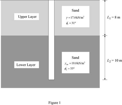
The diameter of the driven pile D is 450 mm.
The length of the pile in the upper layer of the sand
The unit weight of the upper layer sand
The soil friction angle in the lower layer of sand
The length of the pile in the lower layer of the sand
The saturated unit weight of the lower layer sand
The soil friction angle in the lower layer of sand
The soil-pile friction-angle
The coefficient value K is
The factor of safety
Calculation:
Draw the cross section of the pile as in Figure 1.
Calculate the earth pressure coefficient
Here,
Substitute
Calculate the coefficient K for the upper layer using the formula.
Here,
Substitute 0.485 for
Calculate the earth pressure coefficient
Here,
Substitute
Calculate the coefficient K for the lower layer using the formula.
Here,
Substitute 0.455 for
Calculate the area of pile
Substitute 450 mm for D.
Calculate the perimeter p of the pile using the formula.
Substitute 450 mm for D.
Refer Figure (18.12), “Meyerhof’s bearing capacity factor,
Take the value of bearing capacity factor
Calculate the load-carrying capacity
Here,
Take the unit weight of water as
Substitute
Check the calculated value of load-carrying capacity of the pile point using Meyerhof’s equation.
Substitute
Use the lowest of the calculated value of load-carrying capacity of the pile point.
Calculate the soil-pile friction-angle
Substitute
Calculate the soil-pile friction-angle
Substitute
Calculate the critical depth of the pile
Substitute 450 mm for D.
Calculate the unit frictional resistance at the upper layer of sand.
Consider 0 ft from top of the pile.
Calculate the magnitude of unit frictional resistance
Substitute 0 m for z.
The frictional resistance (skin friction)
Consider the pile to the depth of 6.75 m (critical depth of the pile) from the top of pile tip.
Calculate the magnitude of unit frictional resistance
Substitute 6.75 m for z, 0.727 for
Calculate the magnitude of unit frictional resistance
Substitute 6.75 m for z, 0.727 for
Below the upper layer
Calculate the frictional resistance (skin friction)
Substitute 1.414 m for p, 6.75 m for
Calculate the frictional resistance (skin friction)
Substitute 1.414 m for p, 6.75 m for
Calculate the frictional resistance (skin friction)
Substitute 1.414 m for p, 10 m for
Calculate the ultimate load on the pile
Substitute 146.51 kN for
Calculate the allowable load on the pile
Substitute 1,125.27 kN for
Therefore, the load carrying capacity of the pile is
Want to see more full solutions like this?
Chapter 18 Solutions
EBK FUNDAMENTALS OF GEOTECHNICAL ENGINE


- The given beam has continuous lateral support. If the live load is twice the dead load, what is the maximum total service load, in kips / ft, that can be supported? A992 steel is used: Fy = 50 ksi, Fu=65 ksi. Take L = 30 ft. bf For W40 x 149: 2tf = 7.11, = = 54.3, Z 598 in.³ tw W W40 X 149 L (Express your answers to three significant figures.) a. Use LRFD. Wtotal = kips/ft b. Use ASD. Wtotal kips/ftarrow_forwardThe beam shown in the figure below is a W16 × 31 of A992 steel and has continuous lateral support. The two concentrated loads are service live loads. Neglect the weight of the beam and determine whether the beam is adequate. Suppose that P = 52 k. For W16 × 31: d = 15.9 in., tw = 0.275 in., h/tw = 51.6, and M = M₁ = 203 ft-kip, Mn/₁ = Mp/α = 135 ft-kip. P Р W16 x 31 a. Use LRFD. Calculate the required moment strength, the allowable shear strength, and the maximum shear. (Express your answers to three significant figures.) Mu = OvVn = ft-kip kips kips Vu = Beam is -Select- b. Use ASD. Calculate the required moment strength, the allowable shear strength, and the maximum shear. (Express your answers to three significant figures.) Ma = Vn/b - Va = Beam is -Select- ft-kip kips kipsarrow_forwardDetermine the smallest value of yield stress Fy, for which a W-, M-, or S-shape from the list below will become slender. bf/2tfh/tw Shape W12 × 72 8.99 22.6 W12 × 26 8.54 47.2 M4 × 6 11.9 22.0 M12 x 11.8 6.81 62.5 M6 × 4.4 5.39 47.0 S24 × 80 4.02 41.4 S10 × 35 5.03 13.4 (Express your answer to three significant figures.) Fy = ksi To which shape does this value apply? -Select- ✓arrow_forward
- Compute the nominal shear strength of an M12 × 11.8 of A572 Grade 60 steel (Fy = 60 ksi). For M12 x 11.8: d = 12 in., tw = 0.177 in., h/tw = 62.5. Vn = kipsarrow_forwardA flexural member is fabricated from two flange plates 1/2 × 71/2 and a web plate 3/8 × 19. The yield stress of the steel is 50 ksi. a. Compute the plastic section modulus Z and the plastic moment Mp with respect to the major principal axis. (Express your answers to three significant figures.) Z = Mp = in. 3 ft-kips b. Compute the elastic section modulus S and the yield moment My with respect to the major principal axis. (Express your answers to three significant figures.) S = My = in.3 ft-kipsarrow_forward= 65 ksi. A W16×36 of A992 steel has two holes in each flange for 7/8-inch-diameter bolts. For A992 steel: Fy = 50 ksi, Fu For a W16×36: bƒ = 6.99 in., tƒ = 0.430 in., Z = 64.0 in.³ and Sx = 56.5 in.³ a. Assuming continuous lateral support, verify that the holes must be accounted for and determine the nominal flexural strength. (Express your answer to three significant figures.) Mn = ft-kips b. What is the percent reduction in strength? (Express your answer to three significant figures.) Reduction = %arrow_forward
- Find the reinforcements for the mid span and supports for an interior 9 in. thick slab (S-2) in thefloor from Problem 1. Ignore the beams and assume that the slab is supported by columns only (i.e.a flat plate). Sketch the slab and show the reinforcements including the shrinkage andtemperature reinforcement steel. Use f c’ = 4,000 psi and f y = 60,000 psi.NOTE: Problem 3 requires additional column placements at locations such as C and D. The stripof slab between these two columns will behave as a beam support to the one-way slab (with 10 ft.span). Problem 1. The figures below shows the framing plan and section of a reinforced concrete floor system.Floor beams are shown as dotted lines. The weight of the ceiling and floor finishing is 6 psf,that of the mechanical and electrical systems is 7 psf, and the weight of the partitions is 180psf. The floor live load is 105 psf. The 7 in. thick slab exterior bay (S-1) is reinforced with #5rebars @ 10 in. o.c. as the main positive…arrow_forward1- A study of freeway flow at a particular site has resulted in a calibrated speed-density relationship, as follows u = 57.5(10.008k) a) Find the free-flow speed and jam density b) Derive the equations describing flow versus speed and flow versus density c) Determine the capacity of the road 2- A rural freeway has a demand volume of 6750 v/hr. It has four 3.4 m lanes in each direction. The traffic stream is comprised of 8% heavy vehicles and a PHF of 0.94. The terrain is rolling throughout the segment. What is the level of service for the facility? What is the capacity? 3- For an urban freeway, how many 3.6 m lanes in each direction are needed to achieve LOS C on a freeway with a peak hour traffic volume of 5725 v/hr and with a PHF = 0.967 The traffic stream is comprised of 11% heavy vehicles and the location is level terrain.arrow_forwardNote: Provide a clear, step-by-step simplified handwritten solution (with no extra explanations) that is entirely produced by hand without any AI help. I require an expert-level answer, and I will assess it based on the quality and accuracy of the work, referring to the attached image for additional guidance. Make sure every detail is carefully verified for correctness before you submit. Thanks!.arrow_forward
 Principles of Foundation Engineering (MindTap Cou...Civil EngineeringISBN:9781337705028Author:Braja M. Das, Nagaratnam SivakuganPublisher:Cengage Learning
 Fundamentals of Geotechnical Engineering (MindTap...Civil EngineeringISBN:9781305635180Author:Braja M. Das, Nagaratnam SivakuganPublisher:Cengage Learning
 Principles of Foundation Engineering (MindTap Cou...Civil EngineeringISBN:9781305081550Author:Braja M. DasPublisher:Cengage Learning
 Principles of Geotechnical Engineering (MindTap C...Civil EngineeringISBN:9781305970939Author:Braja M. Das, Khaled SobhanPublisher:Cengage Learning