
EBK FUNDAMENTALS OF GEOTECHNICAL ENGINE
5th Edition
ISBN: 8220101425829
Author: SIVAKUGAN
Publisher: CENGAGE L
expand_more
expand_more
format_list_bulleted
Concept explainers
Videos
Textbook Question
Chapter 18, Problem 18.12P
Determine the maximum load that can be allowed on the 450 mm diameter pile shown in Figure 18.36, with a safety factor of 3. Use the a method for computing the shaft friction.
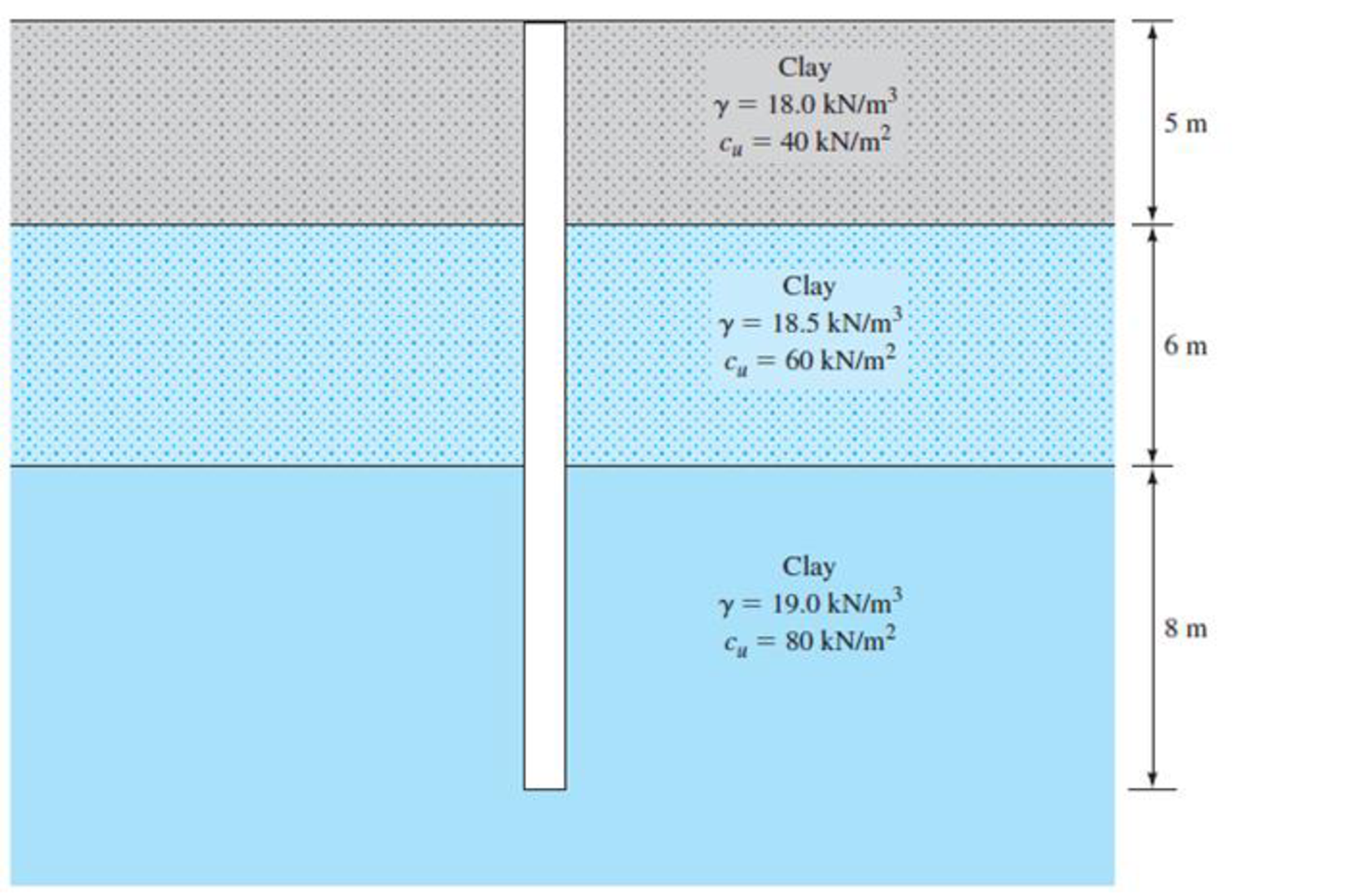
FIG. 18.36
Expert Solution & Answer

Trending nowThis is a popular solution!

Students have asked these similar questions
Note:
Provide a clear, step-by-step simplified handwritten solution (with no extra explanations) that is entirely produced by hand without any AI help. I require an expert-level answer, and I will assess it based on the quality and accuracy of the work, referring to the attached image for additional guidance. Make sure every detail is carefully verified for correctness before you submit. Thanks!.
Example 3 Design a rectangular reinforced concrete beam having a 6 m simple span. A service dead load of 25 kN/m (not including the beam weight) and a service live load 10kn/m are to be supported. use f'c = 25 MPa and fy = 420MPa
Note:
Chapter 18 Solutions
EBK FUNDAMENTALS OF GEOTECHNICAL ENGINE
Ch. 18 - State whether the following are true or false. a....Ch. 18 - A 1500 kN load was applied on two 20 m long and...Ch. 18 - A 500 mm diameter and 20 m long concrete pile is...Ch. 18 - A 400-mm diameter and 15 m long concrete pile is...Ch. 18 - A 400 mm 400 mm square precast concrete pile of...Ch. 18 - Prob. 18.6PCh. 18 - Prob. 18.7PCh. 18 - Prob. 18.8PCh. 18 - Determine the maximum load that can be allowed on...Ch. 18 - Prob. 18.10P
Ch. 18 - Redo Problem 18.10 using the method for...Ch. 18 - Determine the maximum load that can be allowed on...Ch. 18 - Prob. 18.13PCh. 18 - A steel pile (H-section; HP 360 1.491; see Table...Ch. 18 - A concrete pile is 18 m long and has a cross...Ch. 18 - Prob. 18.16PCh. 18 - Prob. 18.17PCh. 18 - Prob. 18.18PCh. 18 - Prob. 18.19PCh. 18 - Figure 18.26a shows a pile. Let L = 20 m, D = 450...Ch. 18 - Refer to Figure 18.26b. Let L = 15.24 m, fill =...Ch. 18 - Prob. 18.22PCh. 18 - Figure 18.39 shows a 3 5 pile group consisting of...Ch. 18 - The section of a 4 4 group pile in a layered...Ch. 18 - Prob. 18.25PCh. 18 - Prob. 18.26CTP
Knowledge Booster


Learn more about
Need a deep-dive on the concept behind this application? Look no further. Learn more about this topic, civil-engineering and related others by exploring similar questions and additional content below.Similar questions
- Note:arrow_forward3. Find the reinforcements for the mid span and supports for an interior 8 in. thick slab (S-2) in the floor from Problem 1. Ignore the beams and assume that the slab is supported by columns only. Sketch the slab and show the reinforcements including the shrinkage and temperature reinforcement steel. Use fc’ = 4,000 psi and fy = 60,000 psi.arrow_forwardProblem 4 (Apx Method) Determine (approximately) the force in each member of the truss. Assume the diagonals can support both tensile and compressive forces. 3 m 50 kN F 000 40 kN 000 000 000 000 000 000 E 000 000 000 000 000 B 3 m 20 kN D 000 000 000 000 C 3 m Problem 5 (Apx Method) Determine (approximately) the force in each member of the truss in problem 4. Assume the diagonals cannot support compressive forces.arrow_forward
- The single degree of freedom (SDOF) system the acceleration at the base (excitation) and the acceleration at the roof (response) of the SDOF system was recorded with sampling rate 50 Hz (50 samples per second, or dt= 0.02 seconds). The file ElCentro.txt includes the two columns of acceleration data. The first column lists the acceleration at the base of the SDOF system. The second column lists the acceleration at the roof of the SDOF system. (a) Plot the time histories of the recorded accelerations at the base and at the roof of the SDOF system. (b) Compute the acceleration, velocity and displacement time histories of the roof of the SDOF system subjected to the recorded base acceleration using the Central Difference method. Plot the accel- eration, velocity and displacement time histories. Plot the restoring force, the damping force, and the inertia force time histories. Compare the recorded acceleration time history at the roof of the SDOF with the acceleration that you computed…arrow_forwardProblem 2 (Using force method) Determine the force in each member of the truss. E = 29000 ksi 3 k 1.5 in² 4 ft 1.5 in² 1.5 in² 2 in² 6 k D 1.5 in² 3 ft 2 in² Barrow_forwardThe single degree of freedom (SDOF) system that you studied under free vibration in Assignment #3 - Laboratory Component has been subjected to a strong ground motion. The acceleration at the base (excitation) and the acceleration at the roof (response) of the SDOF system was recorded with sampling rate 50 Hz (50 samples per second, or dt= 0.02 seconds). The file ElCentro.txt includes the two columns of acceleration data. The first column lists the acceleration at the base of the SDOF system. The second column lists the acceleration at the roof of the SDOF system. (a) Plot the time histories of the recorded accelerations at the base and at the roof of the SDOF system. (b) Compute the acceleration, velocity and displacement time histories of the roof of the SDOF system subjected to the recorded base acceleration using the Central Difference method. Plot the accel- eration, velocity and displacement time histories. Plot the restoring force, the damping force, and the inertia force time…arrow_forward
- Please explain step by step and show formulaarrow_forwardPlease explain step by step and show formulaarrow_forwardFor an reinforced concrete two-way slab shown in figure under the load (P). (the slab continuous over all edges - all sides are fixed), Determine (By using yield line theory): A- Draw the Yield line Pattern B- Determine the moment m 3BAT C- Find The required flexural steel to resist the loads causing the slab to collapse if P = 200 KN, fc = 28 MPa, fy = 420 MPa d = 120 mm. Use 10 mm bars. (Pmin = 0.002) 6m 8m >2m->) 3marrow_forward
- 3BAT For an reinforced concrete two-way slab shown in figure under the load (P). (the slab continuous over all edges - all sides are fixed), Determine (By using yield line theory): A- Draw the Yield line Pattern B- Determine the moment m KN, fc Please don't solve in Al anco if P = 200 6m 8m 2m-)) 3marrow_forwardPlease explain step by step and show formulaarrow_forwardPlease explain step by step and show formulaarrow_forward
arrow_back_ios
SEE MORE QUESTIONS
arrow_forward_ios
Recommended textbooks for you
 Fundamentals of Geotechnical Engineering (MindTap...Civil EngineeringISBN:9781305635180Author:Braja M. Das, Nagaratnam SivakuganPublisher:Cengage Learning
 Principles of Foundation Engineering (MindTap Cou...Civil EngineeringISBN:9781337705028Author:Braja M. Das, Nagaratnam SivakuganPublisher:Cengage Learning
 Principles of Foundation Engineering (MindTap Cou...Civil EngineeringISBN:9781305081550Author:Braja M. DasPublisher:Cengage Learning
 Principles of Geotechnical Engineering (MindTap C...Civil EngineeringISBN:9781305970939Author:Braja M. Das, Khaled SobhanPublisher:Cengage Learning
Fundamentals of Geotechnical Engineering (MindTap...
Civil Engineering
ISBN:9781305635180
Author:Braja M. Das, Nagaratnam Sivakugan
Publisher:Cengage Learning
Principles of Foundation Engineering (MindTap Cou...
Civil Engineering
ISBN:9781337705028
Author:Braja M. Das, Nagaratnam Sivakugan
Publisher:Cengage Learning
Principles of Foundation Engineering (MindTap Cou...
Civil Engineering
ISBN:9781305081550
Author:Braja M. Das
Publisher:Cengage Learning
Principles of Geotechnical Engineering (MindTap C...
Civil Engineering
ISBN:9781305970939
Author:Braja M. Das, Khaled Sobhan
Publisher:Cengage Learning
CE 414 Lecture 02: LRFD Load Combinations (2021.01.22); Author: Gregory Michaelson;https://www.youtube.com/watch?v=6npEyQ-2T5w;License: Standard Youtube License