
Concept explainers
Videos
Refer to Figure 18.9. A cantilever sheet pile is driven into a granular soil where the water table is 2 m (L1) below the top of the sand. The properties of the sand are
Find the required actual depth of the sheet pile.
Answer to Problem 18.1P
The required actual depth of the sheet pile is
Explanation of Solution
Given information:
The depth of water level below the sand
The angle of internal friction for sand
The unit weight of the sand
The saturated unit weight of the sand
The depth below the ground level (L) is 6 m.
Calculation:
Show the cross section of cantilever sheet pile with dimensions as in Figure (1).
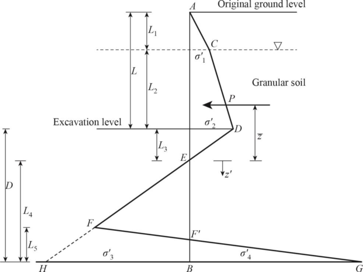
Refer Figure (1),
Find the depth of water table level
Find the rankine active pressure coefficient
Find the rankine passive pressure coefficient
Find the difference between the rankine active pressure coefficient and rankine passive pressure coefficient:
Find the effective unit weight of sand
At the water table level:
Find the intensity of the active pressure to the right of the pile
At the excavation level:
Find the intensity of the active pressure to the right of the pile
Find the depth below the dredge line
Find the area of the pressure diagram (P):
Find the area of the pressure diagram into center of pressure
Find the center of pressure to the area
Find the intensity of the passive pressure
Find the area
Find the area
Find the area
Find the area
Find the depth below point E
Use trial and error method to calculate depth below point E
Try
Substitute 4.30 m for
Hence, the assumption is correct.
The depth below point E is 4.30 m.
Find the depth below the dredge line to bottom of the pile (D):
Increase the depth below the dredge line to bottom of the pile by 30%. The depth below the dredge line to bottom of the pile (D) is 6.214 m.
Find required actual depth of the sheet pile
Thus, the required actual depth of the sheet pile is
Want to see more full solutions like this?
Chapter 18 Solutions
Principles of Foundation Engineering (MindTap Course List)


- please helparrow_forwardAS Q1/ The specific gravity of the soil is 1.41 percentage of water content by weight at field capacity and wilting point are 15% and 7% respectively calculate the equivalent moisture content as equivalent depth for 1.2m root zone : 1. at permanent wilting point 2. at field capacity 3. for ready available waterarrow_forwardQuestion 6 The following figure shows peak-hour volumes for an intersection. Using Webster's method, determine a suitable signal timing for the intersection using the four-phase system shown below. Use an amber interval of 3 seconds and the saturation flow given in the table. O 100 O Phase Lime Group Saturation Flow A e 1615-> 370 3700 B 1615 1615 3700 1615 3700arrow_forward
- PHF-0.91 Pedestrian volume is negligible. Question 7 A parking area with 60 bays has an initial count of 35 vehicles. The in-out survey data for 10-minute intervals is as per the table below. Complete the table, calculate the accumulation, occupancy (%), and parking load (veh.hrs) for each interval. Time (min) In Out Accumulation Occupancy Parking load (%) 0 3 10 2 4 20 1 1 30 1 3 40 1 6 50 1 4 60arrow_forwardQ3/ The following data represent the water depth in the soil of equal areas for specified field. Calculate the uniformity coefficient, efficiency and adequacy of irrigation. Net needed irrigation depth =75 mm (78-04, 79, 88, 85.21, 76,82)arrow_forwardA (A) Q1/ It is required to apply a net depth of 120mm to a total area of 60 ha. The applied discharge is continuously 180 L/s. What must be the time of irrigation? Assume the application efficiency 85%. а Eas 85 0% tarrow_forward
- The following figure is a flexible pavement system with the resilient moduli layer coefficients and drainage coefficients as shown. If the predicted ESAL = 6x10⁶, Reliability, R = 99%, Standard Deviation (So) = 0.45, and APSI = 2.5, select thicknesses D1, D2, and D3 in accordance with the AASHTO Guide for Design of Pavement Structures. E₁ = 400, 000 psi; a₁ = 0.42, Thickness = D₁ E₂=30,000 psi; a₂= 0.14, m₂ = 1.2; Thickness = Dz E=11,000 psi; a=0.08, m3 = 1.2; Thickness = D3 MR= 5,700 psiarrow_forwardDiagramtically show the placement, size, and spacing of temperature steels, dowel bars and tie bars in rigid pavements. Also mention their puproses in rigid pavements.arrow_forwardA six-lane concrete roadway is being designed for a metropolitan area. This roadway will be constructed on a subgrade with an effective modulus of subgrade reaction k of 200 lb/in^3. The ESALs used for the design period is 6.0×10^6. Using the AASHTO design method, determine a suitable thickness of the concrete pavement (to the nearest 1/2 inch), provided that the working stress of the concrete to be used is 600 lb/in^2 and the modulus of elasticity is 6×10^6 lb/in^2. Assume the initial serviceability is 5.0 and the terminal serviceability is 2.0. Assume the overall standard deviation, So, is 0.35, the load transfer coefficient J as 3.2, the drainage coefficient, Cd, is 1.15, and R = 99%.arrow_forward
 Principles of Foundation Engineering (MindTap Cou...Civil EngineeringISBN:9781305081550Author:Braja M. DasPublisher:Cengage Learning
 Fundamentals of Geotechnical Engineering (MindTap...Civil EngineeringISBN:9781305635180Author:Braja M. Das, Nagaratnam SivakuganPublisher:Cengage Learning
 Principles of Foundation Engineering (MindTap Cou...Civil EngineeringISBN:9781337705028Author:Braja M. Das, Nagaratnam SivakuganPublisher:Cengage Learning
 Principles of Geotechnical Engineering (MindTap C...Civil EngineeringISBN:9781305970939Author:Braja M. Das, Khaled SobhanPublisher:Cengage Learning