
Concept explainers
Videos
(a)
The velocity of the wheel’s center at time t.
Answer to Problem 17.70P
Velocity of wheel center at time t will be,
Explanation of Solution
Given:
Wheel is initially at rest and it is relased from an indined surface from rest.
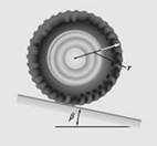
Wheel radius is
The radius of gyration of the wheel is
Initial velocity
Concept used:
Impulse momentum principle,
Moment of inertia
Assume rolling of the wheel without sliding
According to theimpulse-momentum principle,
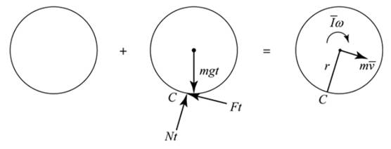
Taking moment about the point of contact C,
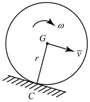
Considering the rolling motion of the wheel,
also a moment of inertia,
putting values in equation (1),
Conclusion:
In this way we can calculate the velocity of the wheel at time t by the impulse-momentum principle and simple calculation,
(b)
The coefficient of static friction needed to overcome the slipping of the wheel.
Answer to Problem 17.70P
Coefficient of friction between wheel and surface needed to overcome slipping of the wheel is
Explanation of Solution
Given:
Wheel radius is
The radius of gyration of the wheel is
Initial velocity
Concept used:
Impulse momentum principle,
Moment of inertia
Assume rolling of the wheel without sliding
Parallel component of inclination
The normal component of indignation
As we know thsat, the coefficient of friction is the ratio of force to the normal reaction between the two objects.
Thus we have,
Conclusion:
Hence, by calculating the normal and parallel component of indignation, we get the value of the coefficient of friction between wheel and slope is
Want to see more full solutions like this?
Chapter 17 Solutions
Vector Mechanics For Engineers


- Q.2: (15 Marks) = 1400 For the following system, determine the first natural frequency using Dunkerley's equation, Given that the disk has moment of inertia J = 2 kg.m², the shaft has G = 20 GPa, p kg/m³, polar moment of cross-sectional area of the shaft Ip = 8×10⁸ m². 500 mm 220 mm k=200 N/m FOF m=1 kg 14.14 56.56. W слarrow_forwardQ1: In Figure below, pinion A having 15 teeth is fixed to motor shaft. Za-20, Z-15, where B and C are a compound gear wheel. Wheel E is keyed to the machine shaft. Arm F rotates about the same shaft on which A is fixed and carries the compound wheel B, C. If the motor runs at 1200 rpm counter-clockwise, find (a) the speed of the machine shaft and (b) ratio of the reduction gear. C B D Q1: A compound epicyclic gear is shown diagrammatically in Figure below. The gears A, D and E are free to rotate on the axis P. The compound gear B and C rotate together on the axis Q at the end of arm F. All the gears have equal pitch. The number of external teeth on the gears A, B and C are 18, 45 and 21 respectively. The gears D and E are annular gears. The gear A rotates at 100 r.p.m. in the anticlockwise direction and the gear D rotates at 450 r.p.m. clockwise. Find the speed and direction of the arm and the gear E. D E A P F LL B Carrow_forwardCalculate the force in cable AB and the angle θ for the support system shown. Round your final answers to two decimal places.arrow_forward
- 1.53 In the steel structure shown, a 6-mm-diameter pin is used at C and 10-mm-diameter pins are used at B and D. The ultimate shearing stress is 150 MPa at all connections, and the ultimate normal stress is 400 MPa in link BD. Knowing that a factor of safety of 3.0 is desired, determine the largest load P that can be applied at A. Note that link BD is not reinforced around the pin holes. Front view D D 6 mm 18 mm B A B Side view 160 mm 120 mm A B Top viewarrow_forwardCORRECT AND DETAILED HANDWRITTEN SOLUTION WITH FBD ONLY. I WILL UPVOTE THANK YOU. CORRECT ANSWER IS ALREADY PROVIDED. 16: Determine (a) the maximum bending stress, (b)the maximum shearing stress, (c) compressive bending stress atthe roller support, and (d) the shearing stress 1 in below the topsurface of the beam at the location 1 ft to the right of the rollersupport in the simply supported beam shown in Fig. 8-70.ANS: (a) 21,945.313 lb/in2; (b) 1656.25 lb/in2; (c) 10,000 lb/in2; (d) 190.972 lb/in2arrow_forwardCORRECT AND DETAILED HANDWRITTEN SOLUTION WITH FBD ONLY. I WILL UPVOTE THANK YOU. CORRECT ANSWER IS ALREADY PROVIDED. 20: A 2022 Porsche 911 (992) GT3 is crossing a 20 ft bridge. The specification of the car is shown below.Determine the maximum shear (in lb) and moment (in lb-ft) on the bridge. ANS: Vmax = 2,680.850 lb ; Mmax = 11,233.13 lb-ftarrow_forward
- CORRECT AND DETAILED HANDWRITTEN SOLUTION WITH FBD ONLY. I WILL UPVOTE THANK YOU. CORRECT ANSWER IS ALREADY PROVIDED. Answers: P1 = 208.625 KN/M P2 = 281.310 KN/M P = 15.491 KN/M FB = 463.402 MPA FV = 55.034 MPAarrow_forwardCORRECT AND DETAILED HANDWRITTEN SOLUTION WITH FBD ONLY. I WILL UPVOTE THANK YOU. CORRECT ANSWER IS ALREADY PROVIDED. 18: Determine the maximum shear and moment that would be experienced by a 10 m beam if a three-wheelmoving load of 10 kN, 30 kN, and 5 kN respectively will pass it by. The distance between the 1st and 2nd load is 1 m and the distance between the 2nd and 3rd load is 3 m.ANS: Vmax = 40 kN ; Mmax = 100.014 kN-marrow_forwardCORRECT AND DETAILED HANDWRITTEN SOLUTION WITH FBD ONLY. I WILL UPVOTE THANK YOU. CORRECT ANSWER IS ALREADY PROVIDED. 5: A 12-m simply supported bridge is constructed with 100-mm concrete slab deck supported by precastconcrete stringers spaced 800 mm on center. Analyze the stringers when subjected to a moving load consisting of 3 evenly spaced axle loads at 3 m and equivalent to 20 kN, 30 kN and 40 kN respectively. The self-weight of the stringers is 8.5 kN/m and the concrete deck has a unit weight of 24 kN/m3 . Neglect all other superimposed loads. Calculate: (a) the maximum shear force in the stringers; (b) the maximum bending moment in the stringers. Answer: Vmax = 135.020 KN, Mmax = 477.388 KN-Marrow_forward
- CORRECT AND DETAILED HANDWRITTEN SOLUTION WITH FBD ONLY. I WILL UPVOTE THANK YOU. CORRECT ANSWER IS ALREADY PROVIDED. 19: A 22-wheeler truck is crossing over 25 m bridge. The dimensions between the axles of the truck are shownin the figure below. Axles 1 to 3 carry a 90 kN load each, axles 4 and 5 carry a 65 kN load each, and the axle directly below the cab of the truck has a load of 100 kN. Determine the maximum shear and moment on the bridge.ANS: Vmax = 374.92 kN ; Mmax = 1,702.229 kN-marrow_forwardCORRECT AND DETAILED HANDWRITTEN SOLUTION WITH FBD ONLY. I WILL UPVOTE THANK YOU. CORRECT ANSWER IS ALREADY PROVIDED. 1. A H = 6 m cantilever retaining wall is subjected to a soil pressurelinearly varying from zero at the top to 90 kPa at the bottom. As an additionalsupport, it is anchored at depth y = 2 m. with maximum tension equal to 25kN. Assume that the stem provides fully retrained support. Draw the shearand moment diagram of the wall to calculate the following: (a) Maximumpositive bending moment per linear meter; (b) maximum negative bendingmoment per linear meter; (c) maximum shear force per linear meter. answer: +MMax = 440 kn-m, -Mmax = 0kn-M, Vmax = 245 KNarrow_forwardCORRECT AND DETAILED HANDWRITTEN SOLUTION WITH FBD ONLY. I WILL UPVOTE THANK YOU. CORRECT ANSWER IS ALREADY PROVIDED. 17: A simply supported beam with the section shown below has an allowableflexural shearing stress of 43 MPa. (a) Determine the maximum allowable shearing force onthe section. And (b) what is the minimum thickness of plate that should be welded at theflanges if the section is to withstand a total shearing force of 200 kN. The additional plate willhave its base dimension equal to the flange dimension.ANS: V = 179.333 kN ; t = 23.181 mmarrow_forward
 Elements Of ElectromagneticsMechanical EngineeringISBN:9780190698614Author:Sadiku, Matthew N. O.Publisher:Oxford University Press
 Mechanics of Materials (10th Edition)Mechanical EngineeringISBN:9780134319650Author:Russell C. HibbelerPublisher:PEARSON
 Thermodynamics: An Engineering ApproachMechanical EngineeringISBN:9781259822674Author:Yunus A. Cengel Dr., Michael A. BolesPublisher:McGraw-Hill Education
 Control Systems EngineeringMechanical EngineeringISBN:9781118170519Author:Norman S. NisePublisher:WILEY
 Mechanics of Materials (MindTap Course List)Mechanical EngineeringISBN:9781337093347Author:Barry J. Goodno, James M. GerePublisher:Cengage Learning
 Engineering Mechanics: StaticsMechanical EngineeringISBN:9781118807330Author:James L. Meriam, L. G. Kraige, J. N. BoltonPublisher:WILEY