
ENGR.MECH.: DYNAMICS-EBOOK>I<
14th Edition
ISBN: 9781292088785
Author: HIBBELER
Publisher: INTER PEAR
expand_more
expand_more
format_list_bulleted
Concept explainers
Videos
Textbook Question
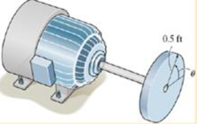
Chapter 16.3, Problem 5P
Determine the number of revolutions, the angular velocity, and angular acceleration of the disk when t = 90 s.
Expert Solution & Answer

Trending nowThis is a popular solution!

Students have asked these similar questions
The 120 kg wheel has a radius of gyration of 0.7 m. A force P with a magnitude of 50 N is applied at the edge of the wheel as seen in the diagram. The coefficient of static friction is 0.3, and the coefficient of kinetic friction is 0.25. Find the acceleration and angular acceleration of the wheel.
Auto Controls
Using MATLAB , find the magnitude and phase plot of the compensators
NO COPIED SOLUTIONS
4-81 The corner shown in Figure P4-81 is initially uniform at 300°C and then suddenly
exposed to a convection environment at 50°C with h 60 W/m². °C. Assume the
=
2
solid has the properties of fireclay brick. Examine nodes 1, 2, 3, 4, and 5 and deter-
mine the maximum time increment which may be used for a transient numerical
calculation.
Figure P4-81
1
2
3
4
1 cm
5
6
1 cm
2 cm
h, T
+
2 cm
Chapter 16 Solutions
ENGR.MECH.: DYNAMICS-EBOOK>I<
Ch. 16.3 - Determine its constant angular acceleration and...Ch. 16.3 - Determine the angular acceleration when it has...Ch. 16.3 - Determine the time it takes to achieve an angular...Ch. 16.3 - If the angular displacement of the wheel is =...Ch. 16.3 - Determine the magnitude of the velocity and...Ch. 16.3 - Determine the velocity of the cylinder and the...Ch. 16.3 - Determine the magnitudes of the velocity and...Ch. 16.3 - If the disk is originally rotating at 0 = 12...Ch. 16.3 - It it is subjected to a constant angular...Ch. 16.3 - If it is subjected to a constant angular...
Ch. 16.3 - Determine the number of revolutions, the angular...Ch. 16.3 - Determine the number of revolutions it must...Ch. 16.3 - Also, find the number of revolutions of gear D to...Ch. 16.3 - Gears A, B, C, and D have radii of 15 mm, 50 mm,...Ch. 16.3 - Determine the magnitude of acceleration of point B...Ch. 16.3 - pulley A is given a constant angular acceleration...Ch. 16.3 - Starting from rest, determine the angular...Ch. 16.3 - If the engine turns pulley A at A = (20t + 40)...Ch. 16.3 - If the engine turns pulley A at A = 60 rad/s,...Ch. 16.3 - Determine the angular velocity of the disk and its...Ch. 16.3 - Determine the magnitudes of the normal and...Ch. 16.3 - Determine the magnitudes of the normal and...Ch. 16.3 - If this gear is initially turning at A = 15 rad/s,...Ch. 16.3 - If this gear is initially turning at A = 15 rad/s,...Ch. 16.3 - Determine the brushs angular velocity when t = 4...Ch. 16.3 - If this gear is initially turning at (A)0 = 20...Ch. 16.3 - Determine the magnitudes of the velocity and the n...Ch. 16.3 - If the motor turns gear A with an angular...Ch. 16.3 - If the motor turns gear A with an angular...Ch. 16.3 - and the meshed pinion gear B on the propeller...Ch. 16.3 - determine the magnitude of the velocity and...Ch. 16.3 - If the gears A and have the dimensions shown,...Ch. 16.3 - and the meshed pinion gear B on the propeller...Ch. 16.3 - and the meshed pinion gear B on the propeller...Ch. 16.3 - If the canisters are centered 200 mm apart on the...Ch. 16.3 - Determine the largest angular velocity of gear B...Ch. 16.3 - The shaft of the motor M turns with an angular...Ch. 16.3 - If A has a constant angular acceleration of A = 30...Ch. 16.3 - If the angular displacement of A it A = (5t3 +...Ch. 16.3 - This gear is connected to gear B, which is fixed...Ch. 16.3 - Express the result in Cartesian vector form.Ch. 16.3 - Determine the velocity and acceleration of point D...Ch. 16.3 - At the instant shown it is rotating about the y...Ch. 16.3 - Determine the magnitudes of the velocity and...Ch. 16.4 - Determine the angular velocity and angular...Ch. 16.4 - Determine the angular acceleration and angular...Ch. 16.4 - Determine the angular acceleration and angular...Ch. 16.4 - Determine the angular velocity and angular...Ch. 16.4 - Determine the angular velocity of the connecting...Ch. 16.4 - The cam rotates with a constant counterclockwise...Ch. 16.4 - The pin connection at O does not cause an...Ch. 16.4 - Determine the velocity of the follower rod AB as...Ch. 16.4 - The pin connection at O does not cause an...Ch. 16.4 - Determine the velocity and acceleration of the peg...Ch. 16.4 - Determine the velocity and acceleration of block...Ch. 16.4 - Determine the angular velocity and angular...Ch. 16.4 - If the slotted arm is causing A to move downward...Ch. 16.4 - If the wedge moves to the left with a constant...Ch. 16.4 - If the rollers do not slip, determine their...Ch. 16.4 - If no slipping occurs between the disk D and the...Ch. 16.4 - Determine the velocity and acceleration of...Ch. 16.5 - If roller A moves to the right with a constant...Ch. 16.5 - Determine the magnitude of the velocity of point B...Ch. 16.5 - The cable wraps around the inner core, and the...Ch. 16.5 - If crank OA rotates with an angular velocity of =...Ch. 16.5 - If rod AB slides along the horizontal slot with a...Ch. 16.5 - Determine the velocity of the peg at B at this...Ch. 16.5 - Determine the velocity of point B at this instant.Ch. 16.5 - If the block at C is moving downward at 4 ft/s,...Ch. 16.5 - Determine the velocity of block C and the angular...Ch. 16.5 - Determine the angular velocities of links A B and...Ch. 16.5 - Also, sketch the position of link BC when = 55,...Ch. 16.5 - Link BC rotates clockwise with an angular velocity...Ch. 16.5 - If the angular velocity of link AB is AB = 3...Ch. 16.5 - Determine the velocity of the gear rack C.Ch. 16.5 - If B is moving to the right at 8 ft/s and C is...Ch. 16.5 - Determine the angular velocity of the gear and the...Ch. 16.5 - Determine the velocity of point A on the rim of...Ch. 16.5 - Link CB is horizontal at this instant.Ch. 16.5 - Determine the velocity of the slider C at the...Ch. 16.5 - Determine the velocity of block C and the angular...Ch. 16.5 - If AB has an angular velocity AB = 8 rad/s,...Ch. 16.5 - If the slider block A is moving downward at vA = 4...Ch. 16.5 - If the slider block A is moving downward at A = 4...Ch. 16.5 - This gear has an inner hub C which is fixed to B...Ch. 16.5 - If link AB is rotating at AB =3 rad/s, determine...Ch. 16.5 - If link CD is rotating at CD = 5 rad/s, determine...Ch. 16.5 - By locking or releasing certain gears, it has the...Ch. 16.5 - If the ring gear A rotates clockwise with an...Ch. 16.5 - It consists of a driving piston A, three links,...Ch. 16.5 - Because of the rotational motion of lint AB and...Ch. 16.6 - Establish the location of the instantaneous center...Ch. 16.6 - Determine the angular velocity of the rod and the...Ch. 16.6 - Determine the angular velocity of link BC and...Ch. 16.6 - The gear rack B is fixed.Ch. 16.6 - If cable AB is unwound with a speed of 3 m/s, and...Ch. 16.6 - Determine the angular velocity of link BC and the...Ch. 16.6 - Determine the angular velocity of links BC and CD...Ch. 16.6 - Assume the geometry is known.Ch. 16.6 - Determine the angular velocity of link AB at the...Ch. 16.6 - Determine the angular velocity of the link CB at...Ch. 16.6 - Determine the velocities of the cylinders center C...Ch. 16.6 - Determine the velocities of points A and B on the...Ch. 16.6 - Determine the velocities of points A and B.Ch. 16.6 - If rod CD is rotating with an angular velocity CD...Ch. 16.6 - If bar AB has an angular velocity AB = 6 rad/s,...Ch. 16.6 - Under these conditions, what is the speed at A if...Ch. 16.6 - Due to slipping, points A and B on the rim of the...Ch. 16.6 - Determine the velocities of the center point C and...Ch. 16.6 - Determine the velocity of point D and the angular...Ch. 16.6 - Determine the velocity of point P, and the angular...Ch. 16.6 - If connected bar CD is rotating with an angular...Ch. 16.6 - Determine the speeds of points A, B, and C caused...Ch. 16.6 - Determine the velocity of the gear rack C.Ch. 16.6 - If the hub gear H and ring gear R have angular...Ch. 16.6 - What is the angular velocity of the spur gear?Ch. 16.6 - Determine the angular velocity of rod CD at the...Ch. 16.6 - If bar CD is rotating with an angular velocity of...Ch. 16.6 - If the link rotates about the fixed point B at 4...Ch. 16.7 - if the sun gear D is rotating clockwise at D = 5...Ch. 16.7 - The angular velocity is given.Ch. 16.7 - Determine the angular acceleration of the rod and...Ch. 16.7 - Determine the acceleration of point A.Ch. 16.7 - At the instant shown, the center O of the gear...Ch. 16.7 - Determine the angular acceleration of the gear at...Ch. 16.7 - Determine the angular acceleration of link BC at...Ch. 16.7 - Determine the angular acceleration of link BC and...Ch. 16.7 - Determine the velocity sod acceleration of the...Ch. 16.7 - Determine the acceleration of the top of the...Ch. 16.7 - Determine the acceleration of the bottom A of the...Ch. 16.7 - Determine the velocity and acceleration of the...Ch. 16.7 - Determine the velocity and acceleration of the...Ch. 16.7 - At the instant shown, point A has the motion...Ch. 16.7 - Determine the angular velocity and angular...Ch. 16.7 - Determine the angular velocity and angular...Ch. 16.7 - Determine the angular acceleration of link AB and...Ch. 16.7 - Determine the angular acceleration of link CD if...Ch. 16.7 - Determine the velocity and acceleration of point A...Ch. 16.7 - Determine the velocity and acceleration of point B...Ch. 16.7 - If it is pulled with a constant velocity v,...Ch. 16.7 - If it does not slip at A, determine the...Ch. 16.7 - If it does not slip at A, determine the...Ch. 16.7 - As cord CF unwinds from the inner rim of the...Ch. 16.7 - Determine the velocity and acceleration of point B...Ch. 16.7 - Determine the angular velocity and angular...Ch. 16.7 - If link DE has the angular motion shown, determine...Ch. 16.7 - If member AB has the angular motion shown,...Ch. 16.7 - If member AB has the angular motion shown,...Ch. 16.7 - Determine the acceleration of points A and B on...Ch. 16.7 - At a given instant, A has a velocity of vA = 4...Ch. 16.7 - Determine the angular acceleration of rod AB at...Ch. 16.8 - Determine the acceleration of A at the instant...Ch. 16.8 - If at the same instant the disk has the angular...Ch. 16.8 - At the same instant, the boom is extending with a...Ch. 16.8 - Prob. 131PCh. 16.8 - Prob. 132PCh. 16.8 - Determine the velocity and acceleration of a water...Ch. 16.8 - At the instant shown, the cord is pulled down...Ch. 16.8 - Prob. 135PCh. 16.8 - Determine the velocity and acceleration of point C...Ch. 16.8 - Prob. 137PCh. 16.8 - Determine the magnitudes of the velocity and...Ch. 16.8 - If link AD is rotating at a constant rate of AD =...Ch. 16.8 - Determine the angular velocity and angular...Ch. 16.8 - If rod AB has an angular velocity of 2 rad/s and...Ch. 16.8 - Prob. 142PCh. 16.8 - If the gears center O moves with the velocity and...Ch. 16.8 - Prob. 144PCh. 16.8 - Prob. 145PCh. 16.8 - Also at this instant the car mounted at the end of...Ch. 16.8 - If the slider block C is fixed to the disk that...Ch. 16.8 - Determine the velocity and acceleration of car A...Ch. 16.8 - Determine the velocity and acceleration of car B...Ch. 16.8 - Link AB has a pin at B which is confined to move...Ch. 16.8 - Prob. 151PCh. 16.8 - The star wheel A makes one sixth of a revolution...Ch. 16.8 - If the tires do not slip on the pavement,...Ch. 16.8 - Determine the velocity and deceleration of the...Ch. 16.8 - Determine the speed of block B when it has risen s...Ch. 16.8 - At the instant shown, it has an acceleration of...Ch. 16.8 - If bar AB has an angular velocity AB = 6 rad/s,...Ch. 16.8 - If the cable does not slip on the pulley's...Ch. 16.8 - Determine the acceleration of the pin at C and the...Ch. 16.8 - If it does not slip at A, determine the...Ch. 16.8 - Determine the velocity and acceleration of the...
Knowledge Booster


Learn more about
Need a deep-dive on the concept behind this application? Look no further. Learn more about this topic, mechanical-engineering and related others by exploring similar questions and additional content below.Similar questions
- Auto Controls A union feedback control system has the following open loop transfer function where k>0 is a variable proportional gain i. for K = 1 , derive the exact magnitude and phase expressions of G(jw). ii) for K = 1 , identify the gaincross-over frequency (Wgc) [where IG(jo))| 1] and phase cross-overfrequency [where <G(jw) = - 180]. You can use MATLAB command "margin" to obtain there quantities. iii) Calculate gain margin (in dB) and phase margin (in degrees) ·State whether the closed-loop is stable for K = 1 and briefly justify your answer based on the margin . (Gain marginPhase margin) iv. what happens to the gain margin and Phase margin when you increase the value of K?you You can use for loop in MATLAB to check that.Helpful matlab commands : if, bode, margin, rlocus NO COPIED SOLUTIONSarrow_forwardAuto Controls Hand sketch the root Focus of the following transfer function How many asymptotes are there ?what are the angles of the asymptotes?Does the system remain stable for all values of K NO COPIED SOLUTIONSarrow_forward-400" 150" in Datum 80" 90" -280"arrow_forward
- 7) Please draw the front, top and side view for the following object. Please cross this line outarrow_forwardA 10-kg box is pulled along P,Na rough surface by a force P, as shown in thefigure. The pulling force linearly increaseswith time, while the particle is motionless att = 0s untilit reaches a maximum force of100 Nattimet = 4s. If the ground has staticand kinetic friction coefficients of u, = 0.6 andHU, = 0.4 respectively, determine the velocityof the A 1 0 - kg box is pulled along P , N a rough surface by a force P , as shown in the figure. The pulling force linearly increases with time, while the particle is motionless at t = 0 s untilit reaches a maximum force of 1 0 0 Nattimet = 4 s . If the ground has static and kinetic friction coefficients of u , = 0 . 6 and HU , = 0 . 4 respectively, determine the velocity of the particle att = 4 s .arrow_forwardCalculate the speed of the driven member with the following conditions: Diameter of the motor pulley: 4 in Diameter of the driven pulley: 12 in Speed of the motor pulley: 1800 rpmarrow_forward
- 4. In the figure, shaft A made of AISI 1010 hot-rolled steel, is welded to a fixed support and is subjected to loading by equal and opposite Forces F via shaft B. Stress concentration factors K₁ (1.7) and Kts (1.6) are induced by the 3mm fillet. Notch sensitivities are q₁=0.9 and qts=1. The length of shaft A from the fixed support to the connection at shaft B is 1m. The load F cycles from 0.5 to 2kN and a static load P is 100N. For shaft A, find the factor of safety (for infinite life) using the modified Goodman fatigue failure criterion. 3 mm fillet Shaft A 20 mm 25 mm Shaft B 25 mmarrow_forwardPlease sovle this for me and please don't use aiarrow_forwardPlease sovle this for me and please don't use aiarrow_forward
arrow_back_ios
SEE MORE QUESTIONS
arrow_forward_ios
Recommended textbooks for you
 Elements Of ElectromagneticsMechanical EngineeringISBN:9780190698614Author:Sadiku, Matthew N. O.Publisher:Oxford University Press
 Mechanics of Materials (10th Edition)Mechanical EngineeringISBN:9780134319650Author:Russell C. HibbelerPublisher:PEARSON
 Thermodynamics: An Engineering ApproachMechanical EngineeringISBN:9781259822674Author:Yunus A. Cengel Dr., Michael A. BolesPublisher:McGraw-Hill Education
 Control Systems EngineeringMechanical EngineeringISBN:9781118170519Author:Norman S. NisePublisher:WILEY
 Mechanics of Materials (MindTap Course List)Mechanical EngineeringISBN:9781337093347Author:Barry J. Goodno, James M. GerePublisher:Cengage Learning
 Engineering Mechanics: StaticsMechanical EngineeringISBN:9781118807330Author:James L. Meriam, L. G. Kraige, J. N. BoltonPublisher:WILEY
Elements Of Electromagnetics
Mechanical Engineering
ISBN:9780190698614
Author:Sadiku, Matthew N. O.
Publisher:Oxford University Press
Mechanics of Materials (10th Edition)
Mechanical Engineering
ISBN:9780134319650
Author:Russell C. Hibbeler
Publisher:PEARSON
Thermodynamics: An Engineering Approach
Mechanical Engineering
ISBN:9781259822674
Author:Yunus A. Cengel Dr., Michael A. Boles
Publisher:McGraw-Hill Education
Control Systems Engineering
Mechanical Engineering
ISBN:9781118170519
Author:Norman S. Nise
Publisher:WILEY
Mechanics of Materials (MindTap Course List)
Mechanical Engineering
ISBN:9781337093347
Author:Barry J. Goodno, James M. Gere
Publisher:Cengage Learning
Engineering Mechanics: Statics
Mechanical Engineering
ISBN:9781118807330
Author:James L. Meriam, L. G. Kraige, J. N. Bolton
Publisher:WILEY
Dynamics - Lesson 1: Introduction and Constant Acceleration Equations; Author: Jeff Hanson;https://www.youtube.com/watch?v=7aMiZ3b0Ieg;License: Standard YouTube License, CC-BY