Concept explainers
Videos
Disk B is at rest when it is brought into contact with disk A, which has an initial angular velocity
i.
Angular velocities have are independent of
Answer to Problem 16.44P
Hence proved, the final angular velocities have are independent of
Explanation of Solution
Given:
Disk A, of mass ma radius of disk A, rA
Initial Angular velocity of disk B =
mass of disk B, mB
radius of disk B, rB
Coefficient of kinetic friction =
Concept used:
When the two disks come in contact, a friction force between them comes into play and it causes the disk A to start rotating while accelerating with a certain angular acceleration in anti-clockwise direction. The reaction of the friction force on disk A will be acting on disk B, such that while it will still be rotating in clockwise direction, but with a certain. angular deacceleration. This will continue till the tangential velocity of both the disks become equal. At that point,
While accelerating from rest for disk A,
While deaccelerating from an angular velocity
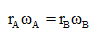
Therefore, condition of velocity equivalence is
Further, Mass moment of inertia for a disk is given by-
The tangential force acting on a disk will provide the angular acceleration to the disk. Therefore,
Mass moment of inertia of disk A =
Mass moment of inertia of disk B =
Friction force between two disks, F =
For disk B,
From eq (2)
For disk A,
From eq(2)
Disk A will continue to deaccelerate, and disk B will continue to accelerate till their tangential acceleration becomes equal.
from eq (1)
From equation (3) and (4), we see that the final angular velocities of the two disks are independent of
Conclusion:
Hence proved, the final angular velocities have are independent of
ii.
Angular velocities in terms of in terms od
Answer to Problem 16.44P
Angular velocity of disk is expressed as
Explanation of Solution
Given:
Disk A, of mass ma radius of disk A, rA
Initial Angular velocity of disk B =
mass of disk B, mB
radius of disk B, rB
Coefficient of kinetic friction =
Concept used:
When the two disks come in contact, a friction force between them comes into play and it causes the disk A to start rotating while accelerating with a certain angular acceleration in anti-clockwise direction. The reaction of the friction force on disk A will be acting on disk B, such that while it will still be rotating in clockwise direction, but with a certain. angular deacceleration. This will continue till the tangential velocity of both the disks become equal. At that point,
While accelerating from rest for disk A,
While deaccelerating from an angular velocity
Therefore, condition of velocity equivalence is
Further, Mass moment of inertia for a disk is given by-
The tangential force acting on a disk will provide the angular acceleration to the disk. Therefore,
Mass moment of inertia of disk A =
Mass moment of inertia of disk B =
Friction force between two disks, F =
For disk B,
From eq (2)
For disk A,
From eq(2)
Disk A will continue to deaccelerate, and disk B will continue to accelerate till their tangential acceleration becomes equal.
from eq (1)
Conclusion:
Angular velocity of disk i
Is expressed as
Want to see more full solutions like this?
Chapter 16 Solutions
Vector Mechanics for Engineers: Dynamics


- reaction at a is 1.6 wL (pos) handwritten solutions only please. correct answers upvotedarrow_forward1 8 4 Add numbers so that the sum of any row or column equals .30 Use only these numbers: .1.2.3.4.5.6.10.11.12.12.13.14.14arrow_forwardUppgift 2 (9p) I77777 20 kN 10 kN/m 4 [m] 2 2 Bestäm tvärkrafts- och momentdiagram för balken i figuren ovan. Extrempunkter ska anges med både läge och värde i diagrammen.arrow_forward
- **Problem 8-45.** The man has a mass of 60 kg and the crate has a mass of 100 kg. If the coefficient of static friction between his shoes and the ground is \( \mu_s = 0.4 \) and between the crate and the ground is \( \mu_c = 0.3 \), determine if the man is able to move the crate using the rope-and-pulley system shown. **Diagram Explanation:** The diagram illustrates a scenario where a man is attempting to pull a crate using a rope-and-pulley system. The setup is as follows: - **Crate (C):** Positioned on the ground with a rope attached. - **Rope:** Connects the crate to a pulley system and extends to the man. - **Pulley on Tree:** The rope runs over a pulley mounted on a tree which redirects the rope. - **Angles:** - The rope between the crate and tree forms a \(30^\circ\) angle with the horizontal. - The rope between the tree and the man makes a \(45^\circ\) angle with the horizontal. - **Man (A):** Pulling on the rope with the intention of moving the crate. This arrangement tests the…arrow_forwardplease solve this problems follow what the question are asking to do please show me step by steparrow_forwardplease first write the line action find the forces and them solve the problem step by steparrow_forward
- please solve this problem what the problem are asking to solve please explain step by step and give me the correct answerarrow_forwardplease help me to solve this problem step by steparrow_forwardplease help me to solve this problem and determine the stress for each point i like to be explained step by step with the correct answerarrow_forward
- please solve this problem for me the best way that you can explained to solve please show me the step how to solvearrow_forwardplese solbe this problem and give the correct answer solve step by step find the forces and line actionarrow_forwardplease help me to solve this problems first write the line of action and them find the forces {fx=0: fy=0: mz=0: and them draw the shear and bending moment diagram. please explain step by steparrow_forward
 Elements Of ElectromagneticsMechanical EngineeringISBN:9780190698614Author:Sadiku, Matthew N. O.Publisher:Oxford University Press
 Mechanics of Materials (10th Edition)Mechanical EngineeringISBN:9780134319650Author:Russell C. HibbelerPublisher:PEARSON
 Thermodynamics: An Engineering ApproachMechanical EngineeringISBN:9781259822674Author:Yunus A. Cengel Dr., Michael A. BolesPublisher:McGraw-Hill Education
 Control Systems EngineeringMechanical EngineeringISBN:9781118170519Author:Norman S. NisePublisher:WILEY
 Mechanics of Materials (MindTap Course List)Mechanical EngineeringISBN:9781337093347Author:Barry J. Goodno, James M. GerePublisher:Cengage Learning
 Engineering Mechanics: StaticsMechanical EngineeringISBN:9781118807330Author:James L. Meriam, L. G. Kraige, J. N. BoltonPublisher:WILEY