
Videos
(a) Obtain y, z, h, and t parameters for the network shown in Fig. 16.67 using either the defining equations or mesh/nodal equations. (b) Verify your answers using the relationships in Table 16.1.
(a)
The
Answer to Problem 59E
The
Explanation of Solution
Given data:
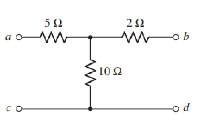
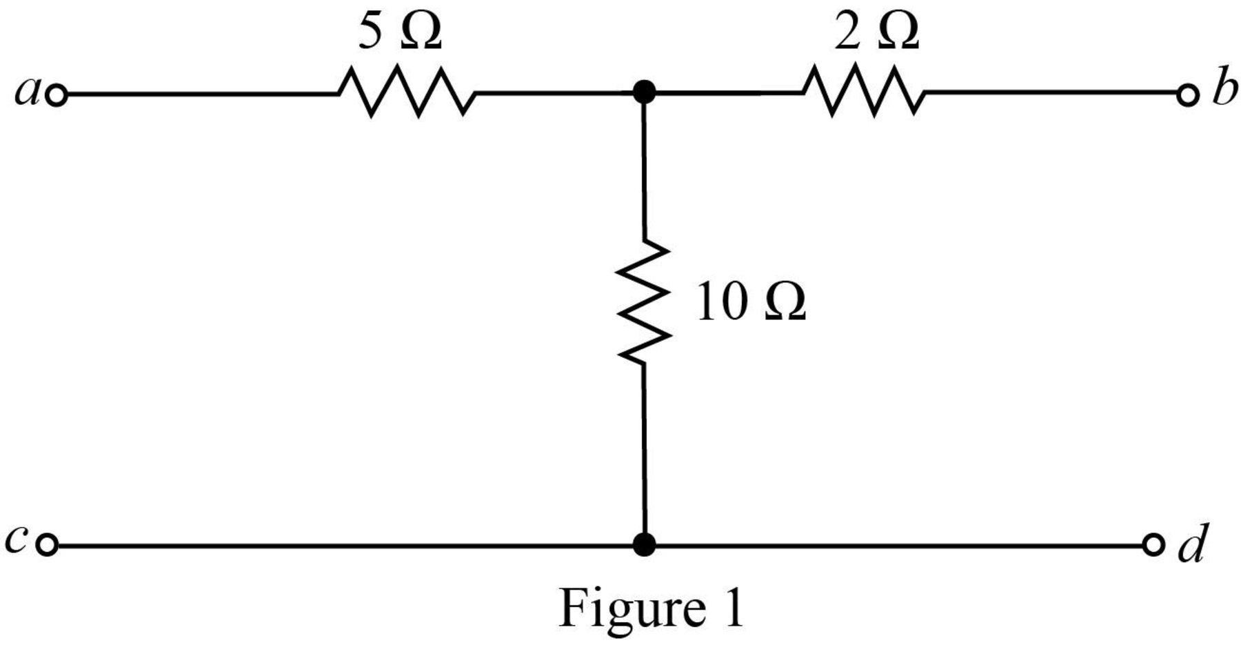
The given diagram is shown in Figure 1.
Calculation:
Mark the branch currents and open circuit voltages.
The required diagram is shown in Figure 2.
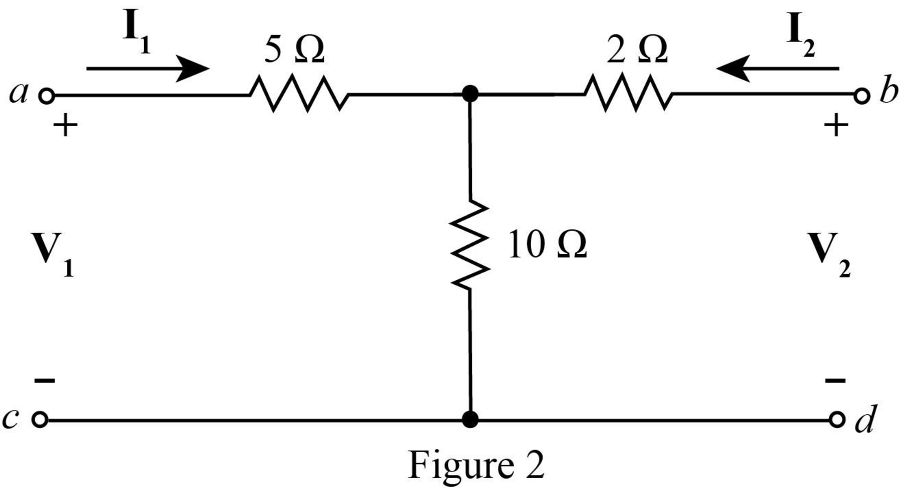
Apply KVL at the input side.
Apply KVL at the output side.
The standard equations for
Compare equation (1) with equation (3).
Compare equation (2) with equation (4).
The
Substitute
Rearrange equation (1) as,
Rearrange equation (2) as,
Substitute
Substitute
The standard equations for
Compare equation (7) with equation (9).
Compare equation (8) with equation (10).
The
Substitute
Substitute
The standard equations for
Compare equation (11) with equation (12).
Compare equation (6) with equation (13).
The
Substitute
Rearrange equation (6) as,
Substitute
The standard equations for
Compare equation (15) with equation (16).
Compare equation (14) with equation (17).
The
Substitute
Conclusion:
Therefore, the
(b)
To verify: The value of
Explanation of Solution
Calculation:
The relation between
The determinant
Substitute
The relation between
Substitute
The relation between
Substitute
Conclusion:
Thus, within the limits of error the value of
Want to see more full solutions like this?
Chapter 16 Solutions
Engineering Circuit Analysis
Additional Engineering Textbook Solutions
Vector Mechanics for Engineers: Statics and Dynamics
Database Concepts (8th Edition)
Electric Circuits. (11th Edition)
Thermodynamics: An Engineering Approach
Vector Mechanics For Engineers
HEAT+MASS TRANSFER:FUND.+APPL.


- What is the open loop transfer function and feedback for thia system? Determine the type of the open loop system. Find the poles s1 and s2 of the open loop system. If the input is a step function R(s)=1/s, find the step response c(t) of the open loop.arrow_forwardnot use ai please don'tarrow_forward2. A DC generator is shown below. This DC generator is driven by a prime mover and rotating in counterclockwise direction. The armature is connected with a load resistor. (i) Using cross (x) or dot (*) to indicate the current direction of each conductor in the armature. (ii) If we want to reverse the polarity of the generated armature voltage, what can we do to? rotation S load Narrow_forward
- 6. The figures below show the equivalent circuit of a separately excited DC generator and the approximate relationship between the flux of main field and exciting current. The field current I can be regulated by the variable resistor Ry, and the battery voltage supplying power to the exciter is 12V. The armature resistance Ro is 20, and the load is 182. For the DC generator, we aim to keep the voltage across the load (RL) constant in different speed range conditions. In the beginning, the flux is 0.12 Wb, the DC generator speed is 1000 rpm, and the generated voltage E。 is 100 V. Calculate: (1) The current flowing through the load. (2) When the speed of generator changes to 1500 rpm, how should we adjust the exciting current Ix to ensure Ę is still 100 V. (Hint: E₁ = Zno/60) (3) When the speed of generator changes to 500 rpm, how should we adjust the exciting current Ix to ensure Eo is still 100 V. (Hint: Eo = Zno/60) Rf ww (Wb) 0.17 0.15 12 V 1x F ele 1 1 2 ell Eo Ro ww 9 w RL Ix (A)arrow_forward7. For a shunt excited motor, the maximum allowable current is twice of the full-load current. The full-load current is 10 A. The equivalent circuit of this motor is also shown below. The rheostat can change the resistance by moving the slider (contact). The counter electromotive force (CEMF) for this motor is 100 V at 1000 rpm. The power supply E, is 200 V. In this case: (1) Calculate the minimum resistor value R at 0 rpm ensuing the motor is running within the safe range, and calculate the power consumed by the rheostat R. (2) Calculate the minimum effective resistor value R at 100 rpm ensuing the motor is running within the safe range, and calculate the power consumed by the rheostat R and the delivered mechanical power. (3) Calculate the minimum resistor value R at 500 rpm ensuing the motor is running within the safe range, and calculate the power consumed by the rheostat R the delivered mechanical power. shunt field R armature rheostat Es + Eoarrow_forward4. For a general DC generator, we aim to achieve constant output voltage at different rotating speeds. (1) List two factors influencing the output voltage for a given DC generator. (2) How does the change of the load (assuming the load is the current flowing though the resistor) will impact on the generated voltage for (a) separately excited DC generator, (b) Shunt DC generator, and (c) cumulative compound DC generator?arrow_forward
- 3. A DC motor is shown below. The armature is supplied by an external battery, and the current flowing direction of each conduction is depicted in the figure. (i) Draw the Lorentz force direction applied on each conductor in the armature. (ii) In which direction will the motor spin? What can we do to reverse the spinning direction? S Narrow_forward5. conditions. For a general DC motor, we aim to control the speed of the motor at different loading (1) List two factors influencing the motor speed for a given DC motor. (2) List three ways to stop a motor and comment on each method?arrow_forwardSolve by Pen and Paper not using chatgptarrow_forward
 Power System Analysis and Design (MindTap Course ...Electrical EngineeringISBN:9781305632134Author:J. Duncan Glover, Thomas Overbye, Mulukutla S. SarmaPublisher:Cengage Learning