
Concept explainers
Find the member end moments and reactions for the frames.
Answer to Problem 31P
The reaction at point A
The end moment at the member
Explanation of Solution
Fixed end moment:
Formula to calculate the relative stiffness for fixed support
Formula to calculate the fixed moment for point load with equal length are
Formula to calculate the fixed moment for point load with unequal length are
Formula to calculate the fixed moment for UDL is
Formula to calculate the fixed moment for UVL are
Formula to calculate the fixed moment for deflection is
Calculation:
Consider the elastic modulus E of the frame is constant.
Show the free body diagram of the entire frame as in Figure 1.
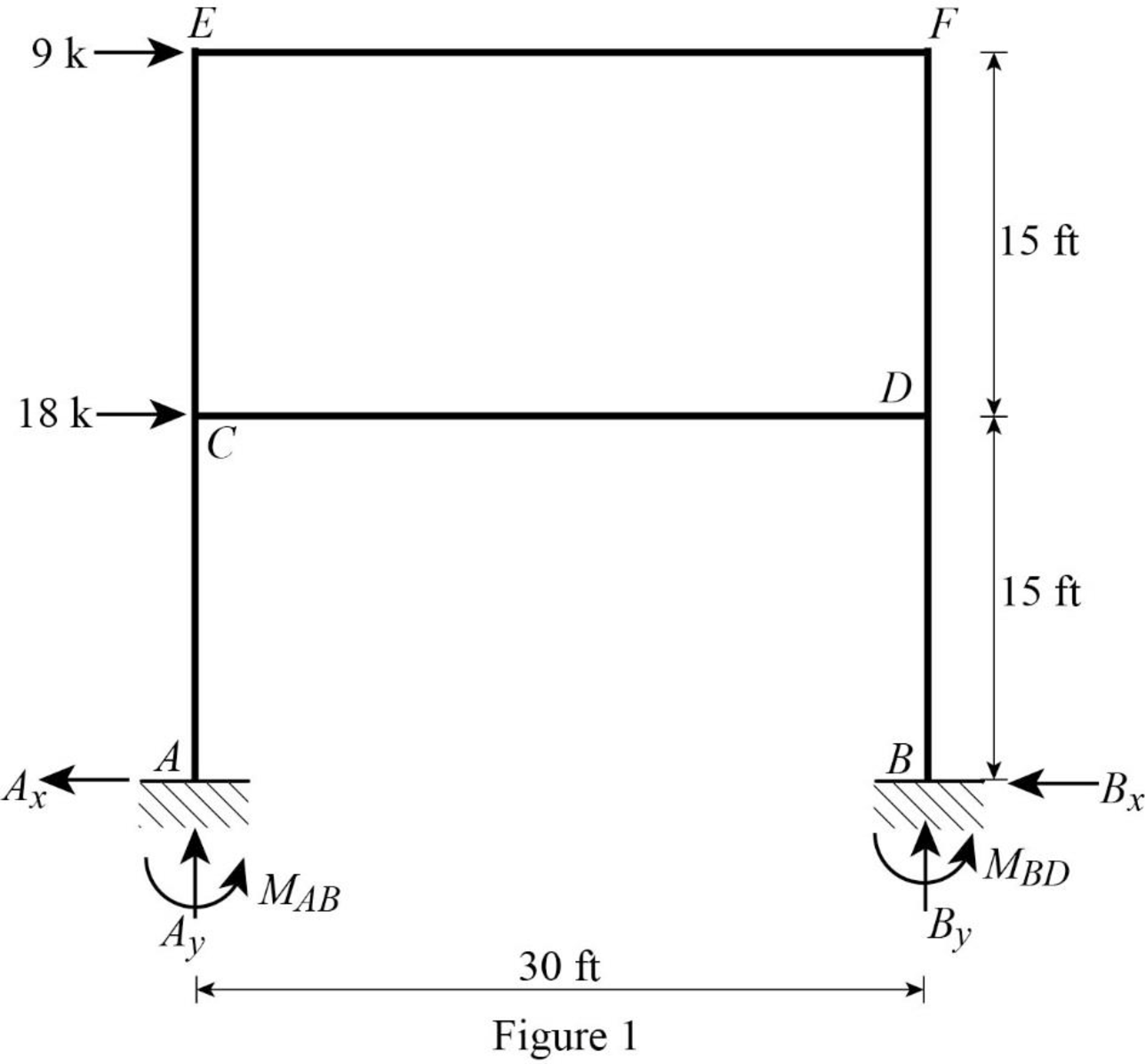
Refer Figure 1,
Calculate the relative stiffness
Calculate the relative stiffness
Calculate the distribution factor
Substitute
Calculate the distribution factor
Substitute
Calculate the distribution factor
Substitute
Check for sum of distribution factor as below:
Substitute
Hence, OK.
Calculate the distribution factor
Substitute
Calculate the distribution factor
Substitute
Check for sum of distribution factor as below:
Substitute
Hence, OK.
Calculate the distribution factor
Substitute
Calculate the distribution factor
Substitute
Check for sum of distribution factor as below:
Substitute
Hence, OK.
Calculate the distribution factor
Substitute
Calculate the distribution factor
Substitute
Calculate the distribution factor
Substitute
Check for sum of distribution factor as below:
Substitute
Hence, OK.
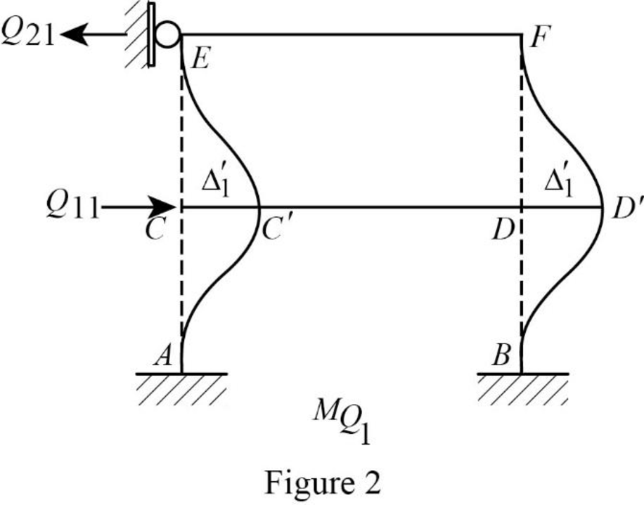
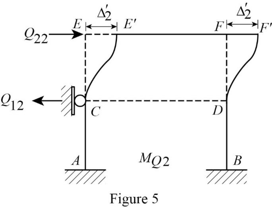
Show the translation
Write the expression to calculate the Fixed-end moment of the member.
Assume the Fixed-end moment of the members AC, CA, BD and DB as
Write the expression to calculate the Fixed-end moment of the member.
Assume the Fixed-end moment of the members CE, EC, DF and FD as
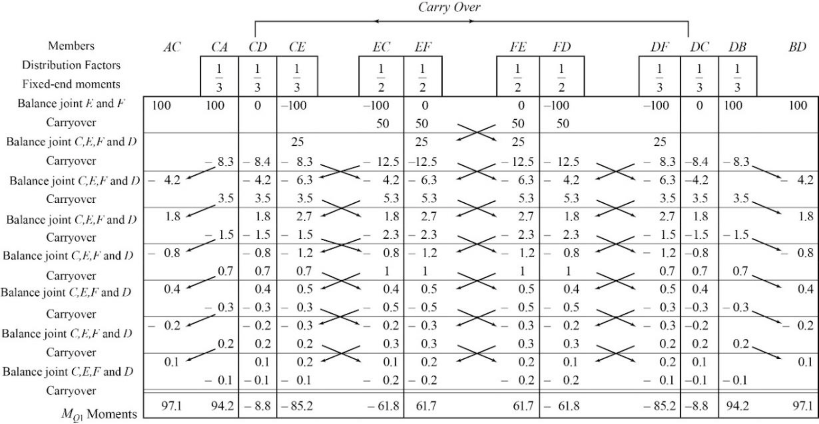
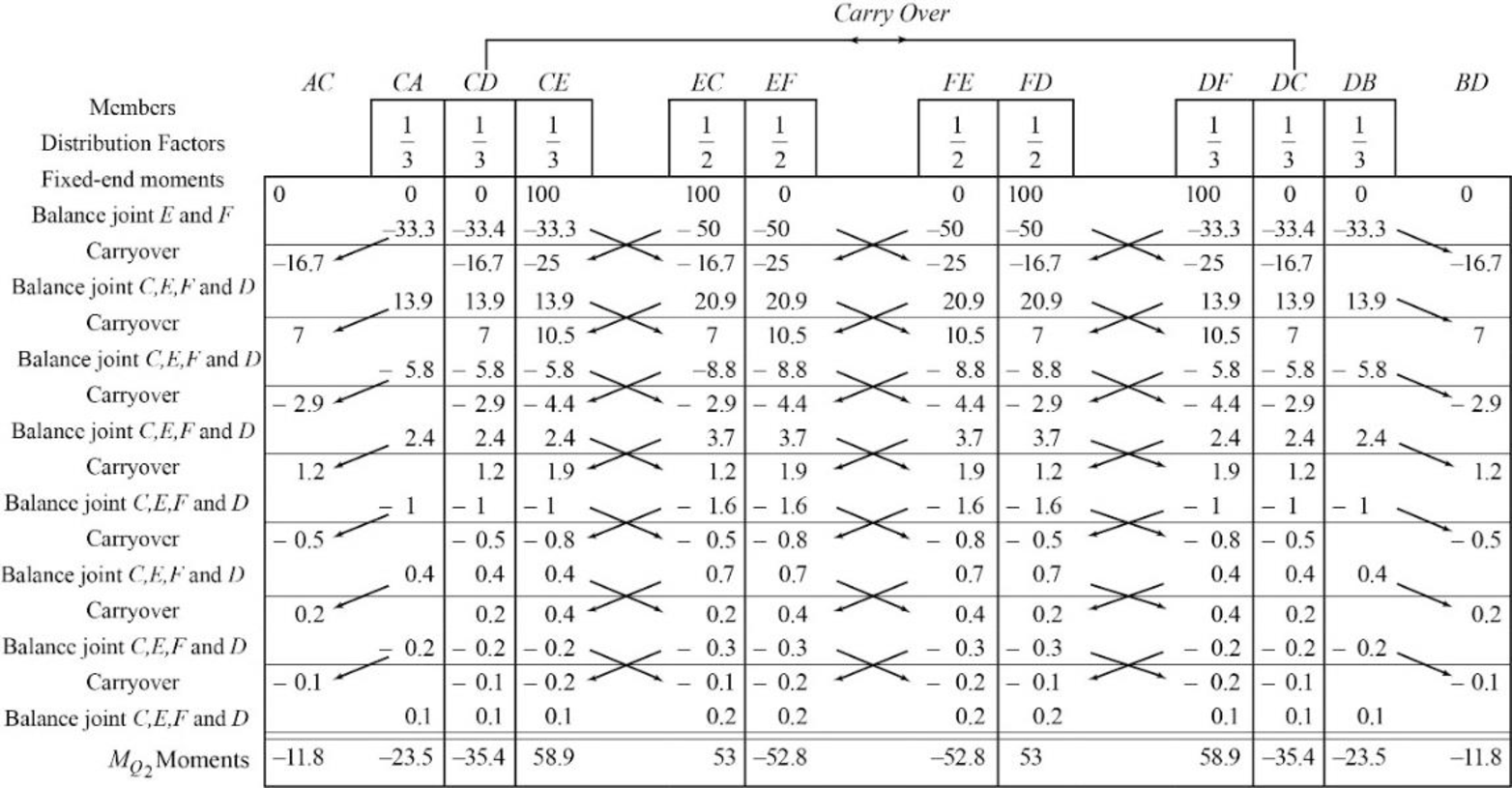
Show the calculation of
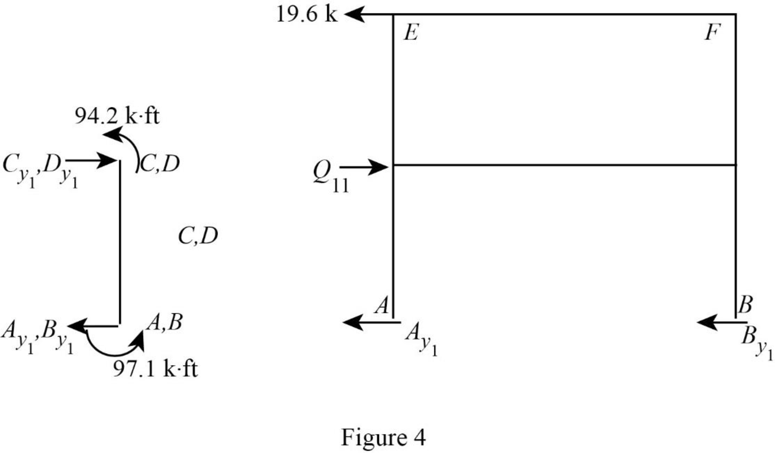
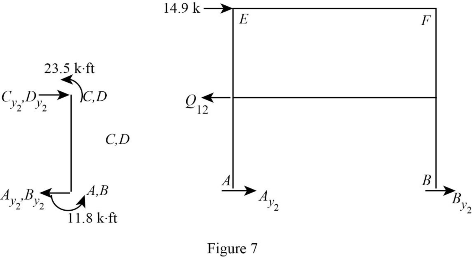
Show the free body diagram of the frame with unknown reaction
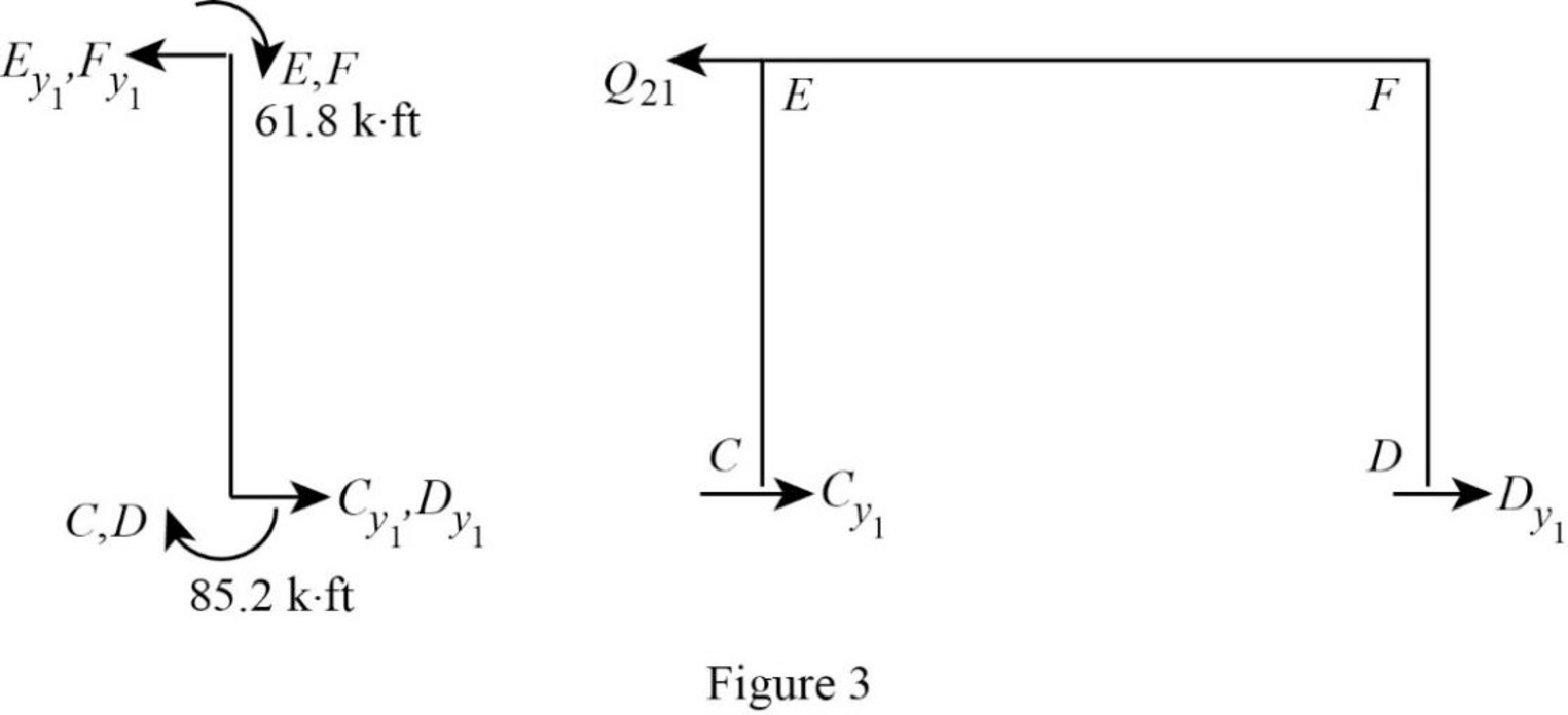
Consider member EC:
Calculate the horizontal reaction at the joint C by taking moment about point E.
Calculate the horizontal reaction at joint E by resolving the horizontal equilibrium.
Consider member FD:
Calculate the horizontal reaction at the joint D by taking moment about point F.
Calculate the horizontal reaction at joint F by resolving the horizontal equilibrium.
Calculate the reaction
Show the free body diagram of the frame with unknown reaction
Consider member AC:
Calculate the horizontal reaction at the joint A by taking moment about point C.
Calculate the horizontal reaction at joint C by resolving the horizontal equilibrium.
Consider member BD:
Calculate the horizontal reaction at the joint B by taking moment about point D.
Calculate the horizontal reaction at joint D by resolving the horizontal equilibrium.
Calculate the reaction
Show the translation
Write the expression to calculate the Fixed-end moment of the member.
Assume the Fixed-end moment of the members CE, EC, DF and FD as
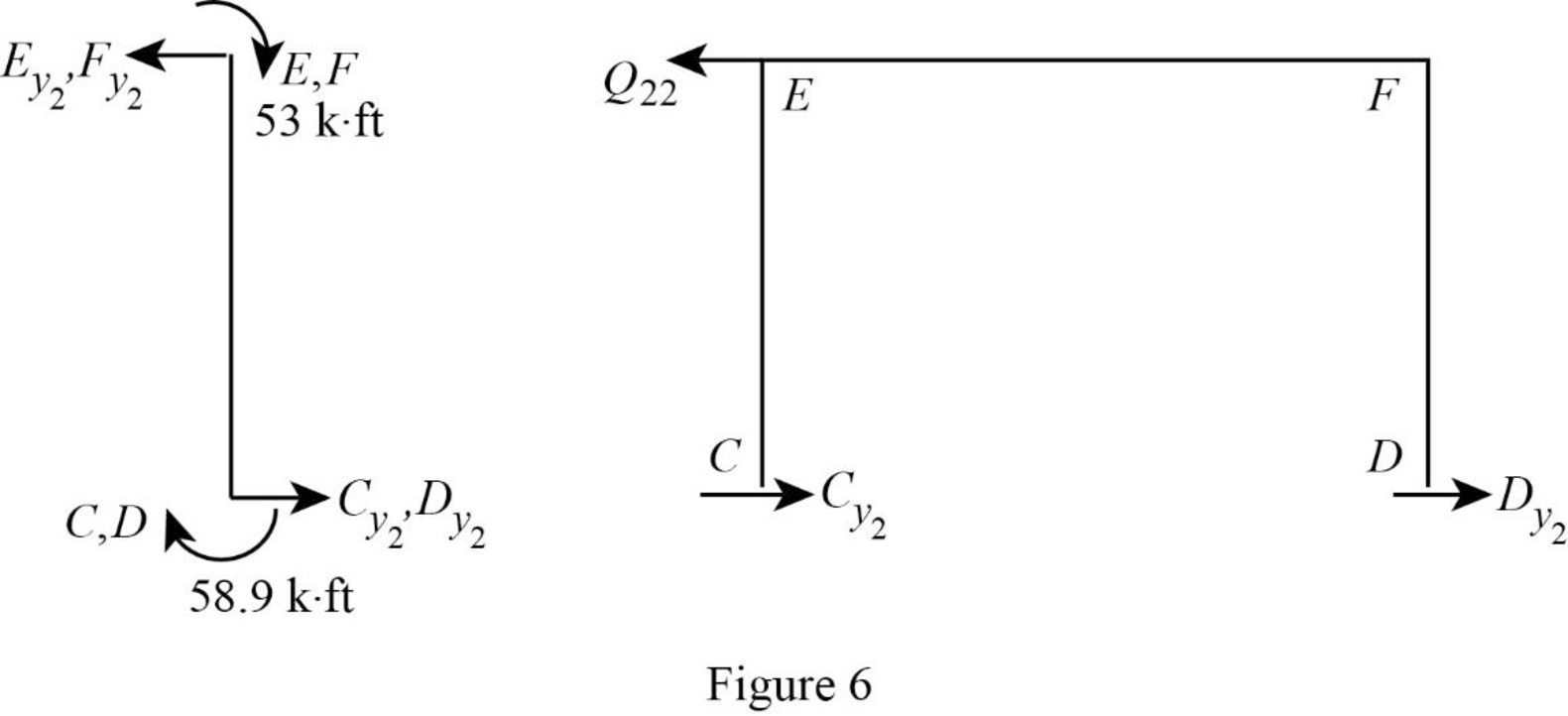
Show the calculation of
Show the free body diagram of the frame with unknown reaction
Consider member EC:
Calculate the horizontal reaction at the joint C by taking moment about point E.
Calculate the horizontal reaction at joint E by resolving the horizontal equilibrium.
Consider member FD:
Calculate the horizontal reaction at the joint D by taking moment about point F.
Calculate the horizontal reaction at joint F by resolving the horizontal equilibrium.
Calculate the reaction
Show the free body diagram of the frame with unknown reaction
Consider member AC:
Calculate the horizontal reaction at the joint A by taking moment about point C.
Calculate the horizontal reaction at joint C by resolving the horizontal equilibrium.
Consider member BD:
Calculate the horizontal reaction at the joint B by taking moment about point D.
Calculate the horizontal reaction at joint D by resolving the horizontal equilibrium.
Calculate the reaction
Write the equation by superimposing the horizontal forces at joints C,
Write the equation by superimposing the horizontal forces at joints E,
Calculate the value of
Calculate the actual member end moments of the member AC and BD:
Substitute
Calculate the actual member end moments of the member CA and DB:
Substitute
Calculate the actual member end moments of the member CD and DC:
Substitute
Calculate the actual member end moments of the member CE and DF:
Substitute
Calculate the actual member end moments of the member EC and FD:
Substitute
Calculate the actual member end moments of the member EC and FD:
Substitute
Show the section free body diagram of the member as in Figure 8.
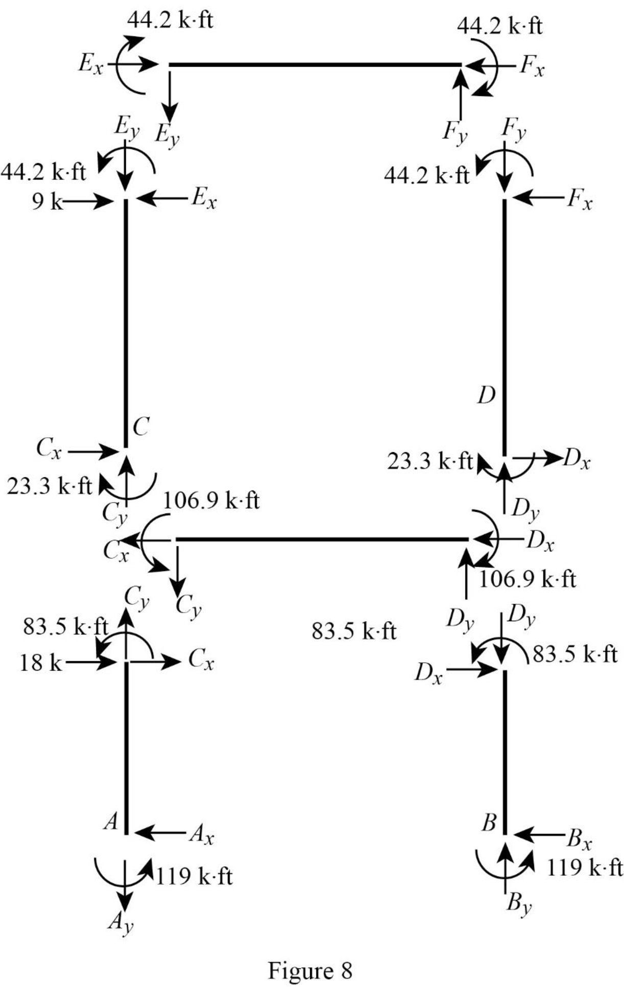
Consider member EF:
Calculate the vertical reaction at the joint E by taking moment about point F.
Calculate the vertical reaction at joint F by resolving the horizontal equilibrium.
Consider member CD:
Calculate the vertical reaction at the joint C by taking moment about point D.
Calculate the vertical reaction at joint D by resolving the horizontal equilibrium.
Calculate the reaction at joint A using the relation:
Calculate the reaction at joint B using the relation:
Consider member AC:
Calculate the horizontal reaction at the joint A by taking moment about point C.
Consider member BD:
Calculate the horizontal reaction at the joint B by taking moment about point D.
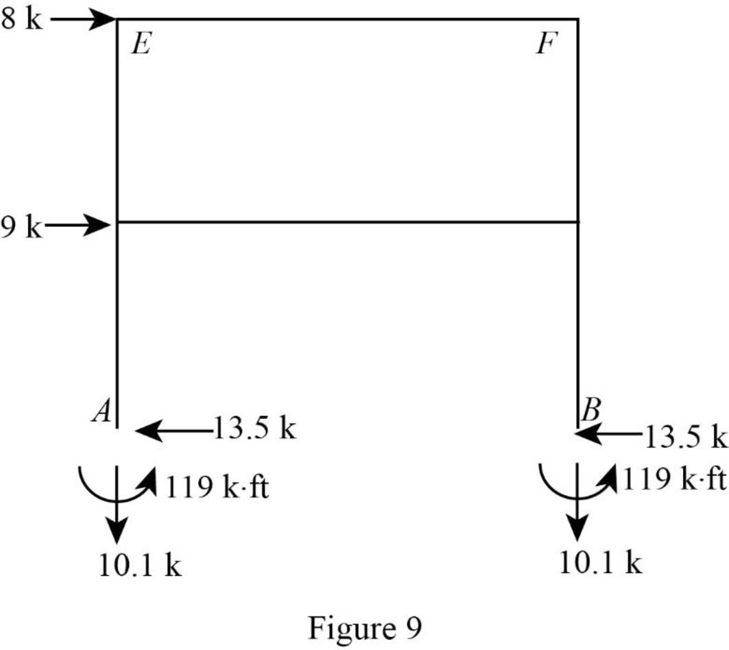
Show the reactions of the frame as in Figure 9.
Want to see more full solutions like this?
Chapter 16 Solutions
Structural Analysis, SI Edition


- 88 L Solle ined sove in peaper 96252 Example 5.5 The turbine rotor of a ship has a mass of 30 tons, a radius of gyration of 600 mm and rotates at 2400 rpm in a clockwise direction when viewed from aft. The ship pitches through a total angle of 15%, 7.5° above and 7.5° below the horizontal, the motion being simple harmonic and having a period of 12 sec. Determine the maximum gyroscopic couple on the holding down bolts of the turbine and the direction of yaw as the bow rises. النص ملصقات -20125 750 31 الرسم X 7.0! 989 Carrow_forwardDesign the deep beam in a wall for a warehouse, as shown in the drawing below using the strength design method of TMS 402-22. The wall is to be constructed of fully grouted hollow concrete masonry units in running bond. Determine the width of the masonry units, and the flexural and shear reinforcement required. Use mf ′ = 2,000 psi and Grade 60 (60 ksi) steel, and Type S Portland cement mortar. In addition to its own weight, it carries a dead load of 1.5 kip/ft. and a live load of 0.2 kip/ft. from the roof. The walls on both sides of the opening are very long. Therefore, you may assume that the beam is fixed from rotation at both ends. Design using the following two methods. (a) Design it as a deep beam with the moment arm z given by the code. Show the layout of the flexural and shear reinforcements with diagrams. (b) Design a masonry lintel beam (not a deep beam) that will carry the weight of the masonry of above, and the dead and live loads from the roof. Determine whether you can…arrow_forwardCivil Engineering Questionarrow_forward
- 6:31 mi Official International Websit maserati.com/global/en Maserati 66 Continue without Accepting Maserati By clicking "Accept All Cookies", you agree to the storing of cookies on your device to enhance site navigation, analyze site usage, and assist in our marketing efforts. Accept All Cookies Cookies Settings INTRODUCING THE ALL-NEW MASERATI GranCabrio DISCOVER MORE > 1/5 Oarrow_forwardJOB UPDATE QUALCOMM FULL STACK DEVELOPER ASSOCIATE INFOR (FRESHERS) IBM QUALITY ENGINEER DATAVAIL DATABASE ADMINISTRATOR INTOUCH CUST SERVICE (CHAT/EMAIL) ACCENTURE Vinkjobs.com #vinkjobs CUSTOMER SUPPORT Search "Vinkjobs.com" on Googlearrow_forwardHello, I would like to ask if the answer provided in this link is correct based on the floor plan shown in the attached pictures? Kindly verify if the solution matches the actual layout and measurements. Thank you! https://www.bartleby.com/questions-and-answers/i-need-help-estimating-the-required-materials-for-masonry-works-using-chb-in-a-2-storey-residential-/bdb70948-ded3-4461-9057-f63a7a1c5f8farrow_forward
- Structural analysis question Cleary explain each step with appropriate solviarrow_forwardAn activity on a non critical path has a total float of 16 days and a duration of 5 days. The start of the activity is delayed by delivery of material for 12 days. A worker shortage makes the activity take 12 days. How far behind the original critical path schedule are you? b.3 days a.0 days d.4 days c.4 days aheadarrow_forwardPlease answer the two questions in detail and as best as you can. Please ensure it is 100% done by human, please do not use AI or chatgpt.arrow_forward
