
Concept explainers
Find the member end moments and reactions for the frames.
Answer to Problem 30P
The reaction at point A
The end moment at the member
Explanation of Solution
Fixed end moment:
Formula to calculate the relative stiffness for fixed support
Formula to calculate the fixed moment for point load with equal length are
Formula to calculate the fixed moment for point load with unequal length are
Formula to calculate the fixed moment for UDL is
Formula to calculate the fixed moment for UVL are
Formula to calculate the fixed moment for deflection is
Calculation:
Consider the flexural rigidity EI of the frame is constant.
Show the free body diagram of the entire frame as in Figure 1.
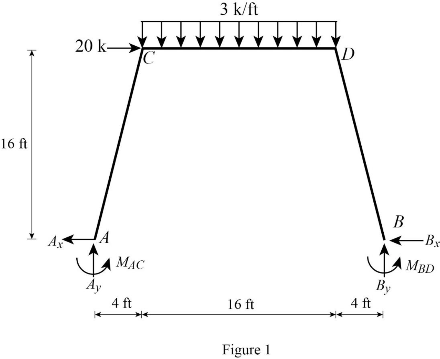
Refer Figure 1,
Calculate the length of the member AC and BD:
Calculate the relative stiffness
Calculate the relative stiffness
Calculate the relative stiffness
Calculate the distribution factor
Substitute
Calculate the distribution factor
Substitute
Check for sum of distribution factor as below:
Substitute 0.492 for
Hence, OK.
Calculate the distribution factor
Substitute
Calculate the distribution factor
Substitute
Check for sum of distribution factor as below:
Substitute 0.508 for
Hence, OK.
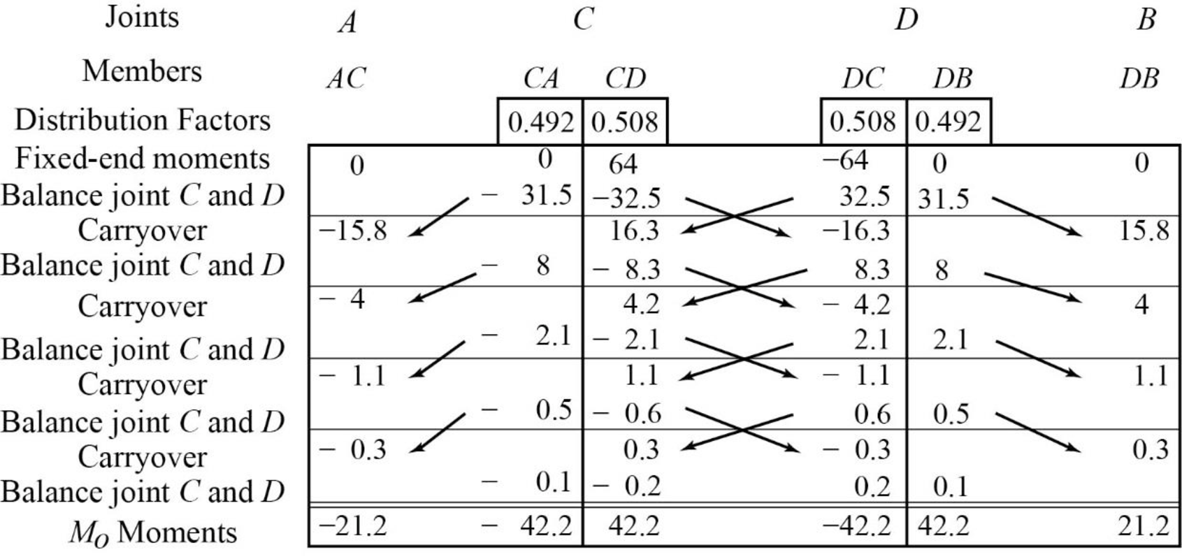
Calculate the fixed end moment for AC and CA.
Calculate the fixed end moment for CD.
Calculate the fixed end moment for DC.
Calculate the fixed end moment for DB and BD.
Show the calculation of
Show the arbitrary translation as in Figure 2.
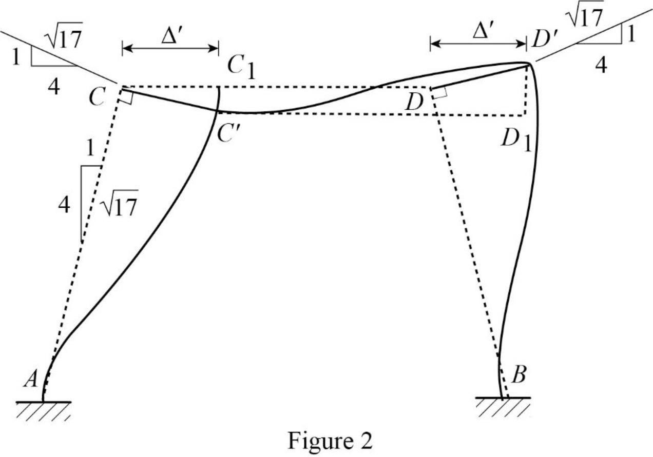
Calculate the relative translation
Calculate the relative translation
Calculate the relative translation
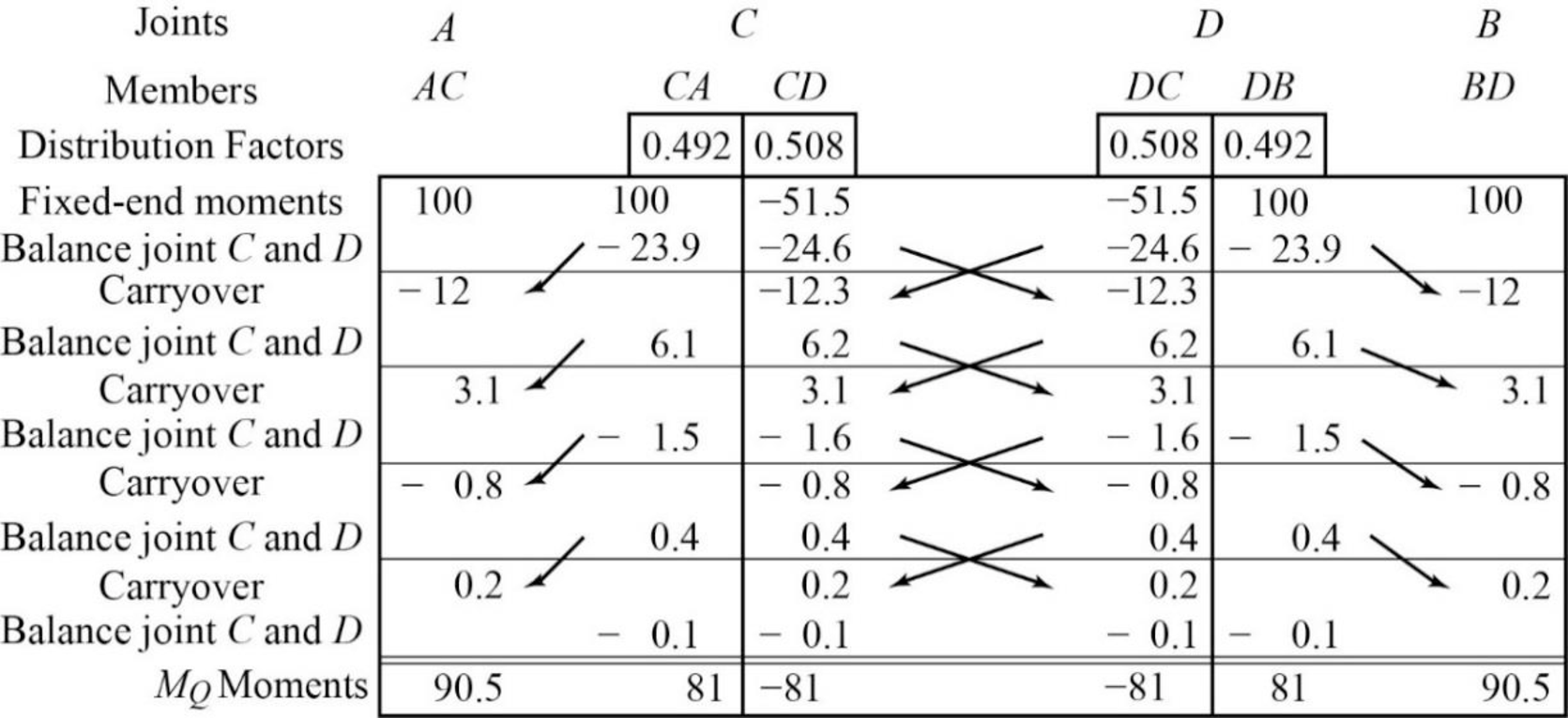
Calculate the fixed end moment for AC and CA.
Substitute
Calculate the fixed end moment for CD and DC.
Substitute
Calculate the fixed end moment for BD and DB.
Substitute
Assume the Fixed-end moment at AC and CA as
Calculate the value of
Substitute
Calculate the fixed end moment of CD and DC.
Substitute 4,395.7 for
Calculate the fixed end moment of BD and DB.
Substitute 4,395.7 for
Show the calculation of
Show the free body diagram of the member AC, CD and DB for side-sway permitted as in Figure 3.
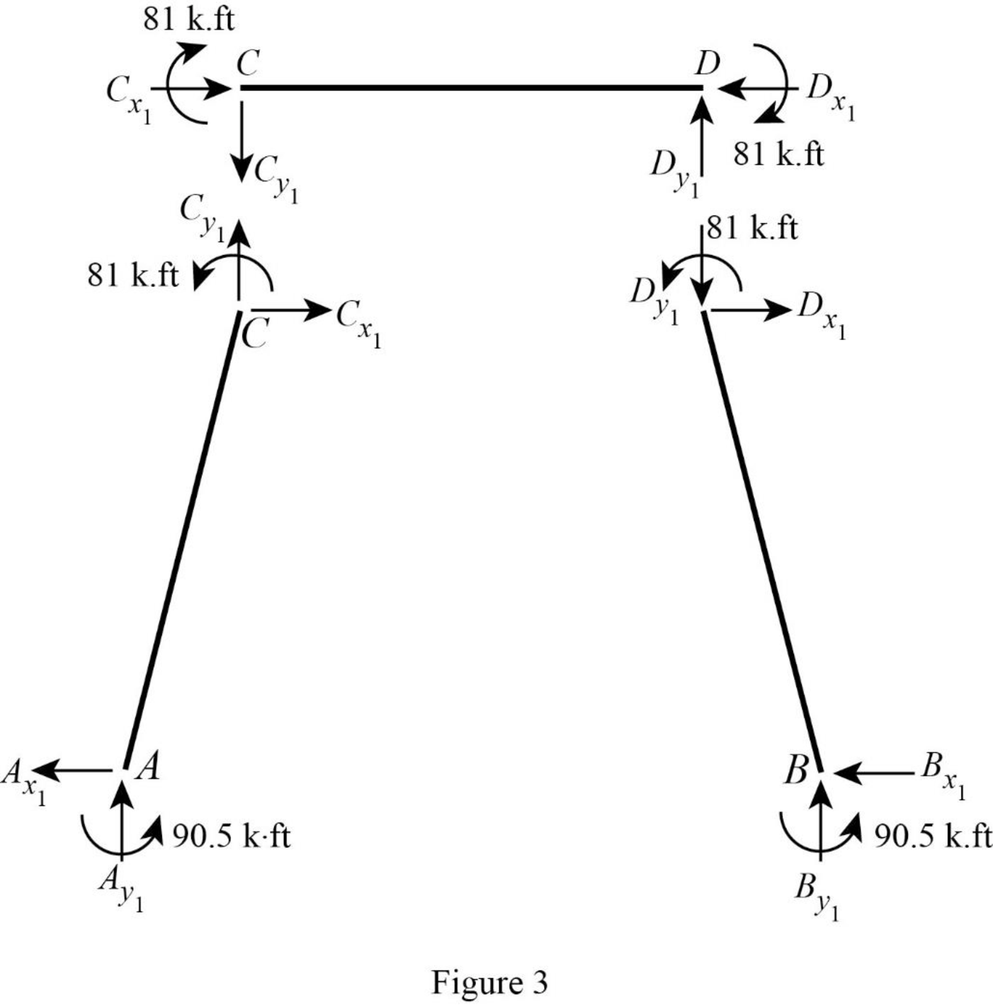
Consider member CD:
Calculate the vertical reaction at the joint C by taking moment about point D.
Calculate the vertical reaction at joint D by resolving the horizontal equilibrium.
Consider member AC
Calculate vertical reaction at joint A using the relation:
Calculate horizontal reaction at joint A by taking moment about point C
Calculate the horizontal reaction at joint C by resolving the horizontal equilibrium.
Consider member DB:
Calculate vertical reaction at joint B using the relation:
Calculate horizontal reaction at joint B by taking moment about point D
Calculate the horizontal reaction at joint D by resolving the horizontal equilibrium.
Show the unknown load Q as in Figure 4.
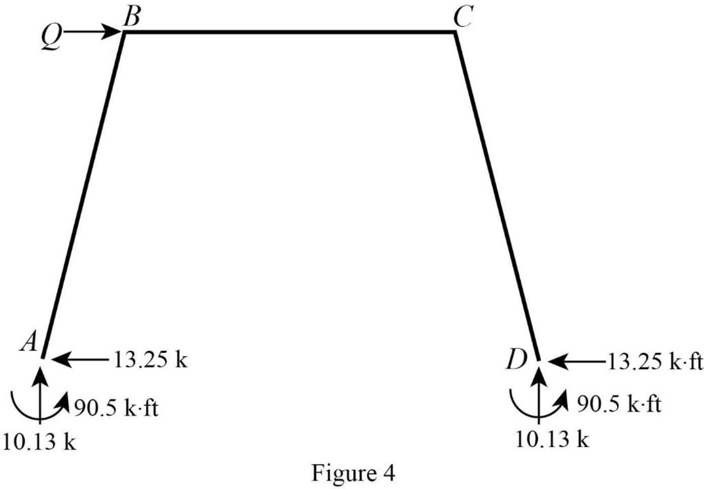
Calculate the reaction R using the relation:
Calculate the actual member end moments of the member AC:
Substitute
Calculate the actual member end moments of the member CA:
Substitute
Calculate the actual member end moments of the member CD:
Substitute
Calculate the actual member end moments of the member DC:
Substitute
Calculate the actual member end moments of the member DB:
Substitute
Calculate the actual member end moments of the member BD:
Substitute
Show the section free body diagram of the member AC, CD and DB as in Figure 5.
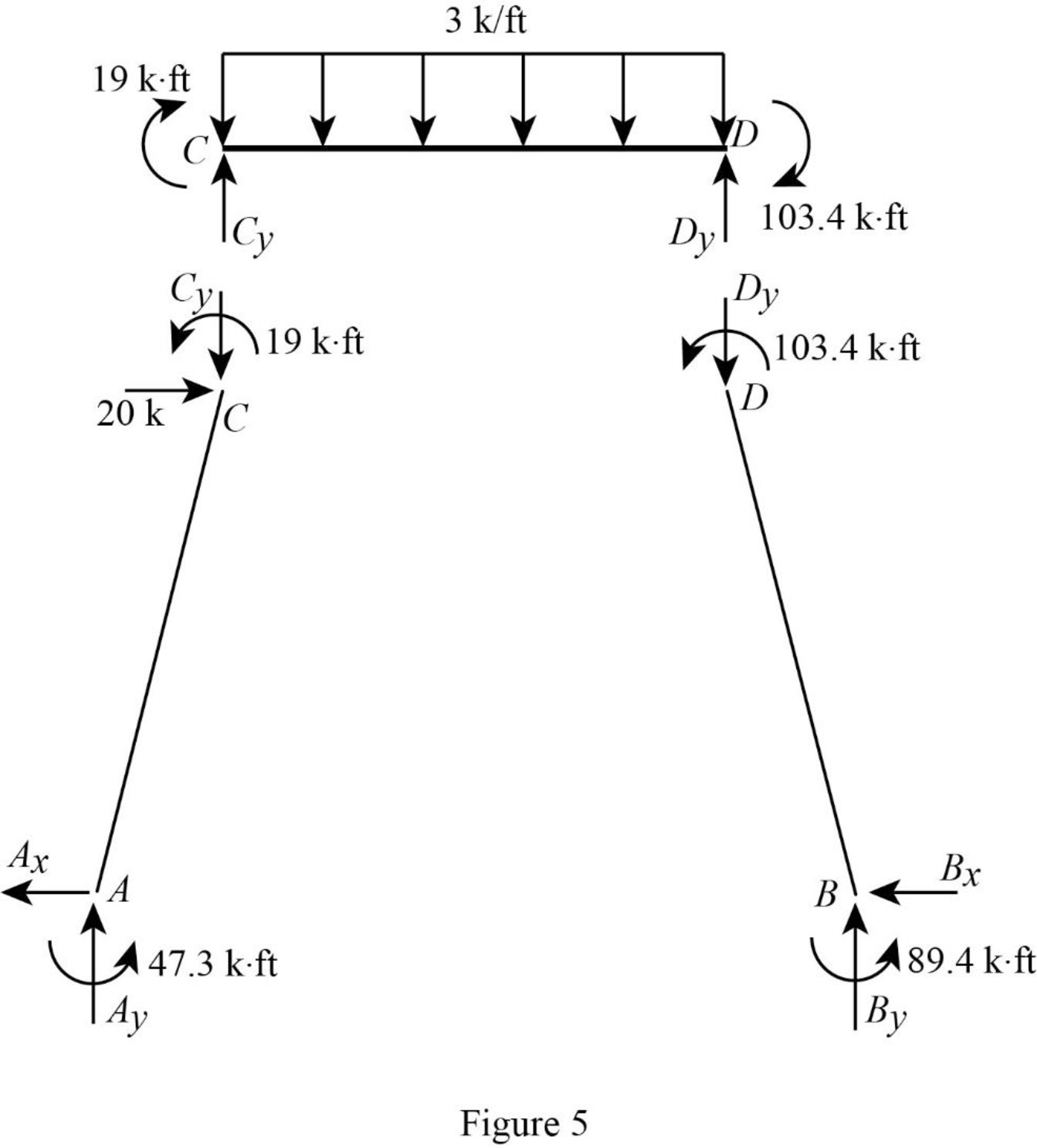
Consider the member CD.
Calculate the vertical reaction at the joint D by taking moment about point C.
Calculate the vertical reaction at joint C by resolving the vertical equilibrium.
Consider the member AC.
Calculate the vertical reaction at joint A by resolving the vertical equilibrium.
Calculate the horizontal reaction at the joint A by taking moment about point C.
Consider the member BD.
Calculate the vertical reaction at joint B by resolving the vertical equilibrium.
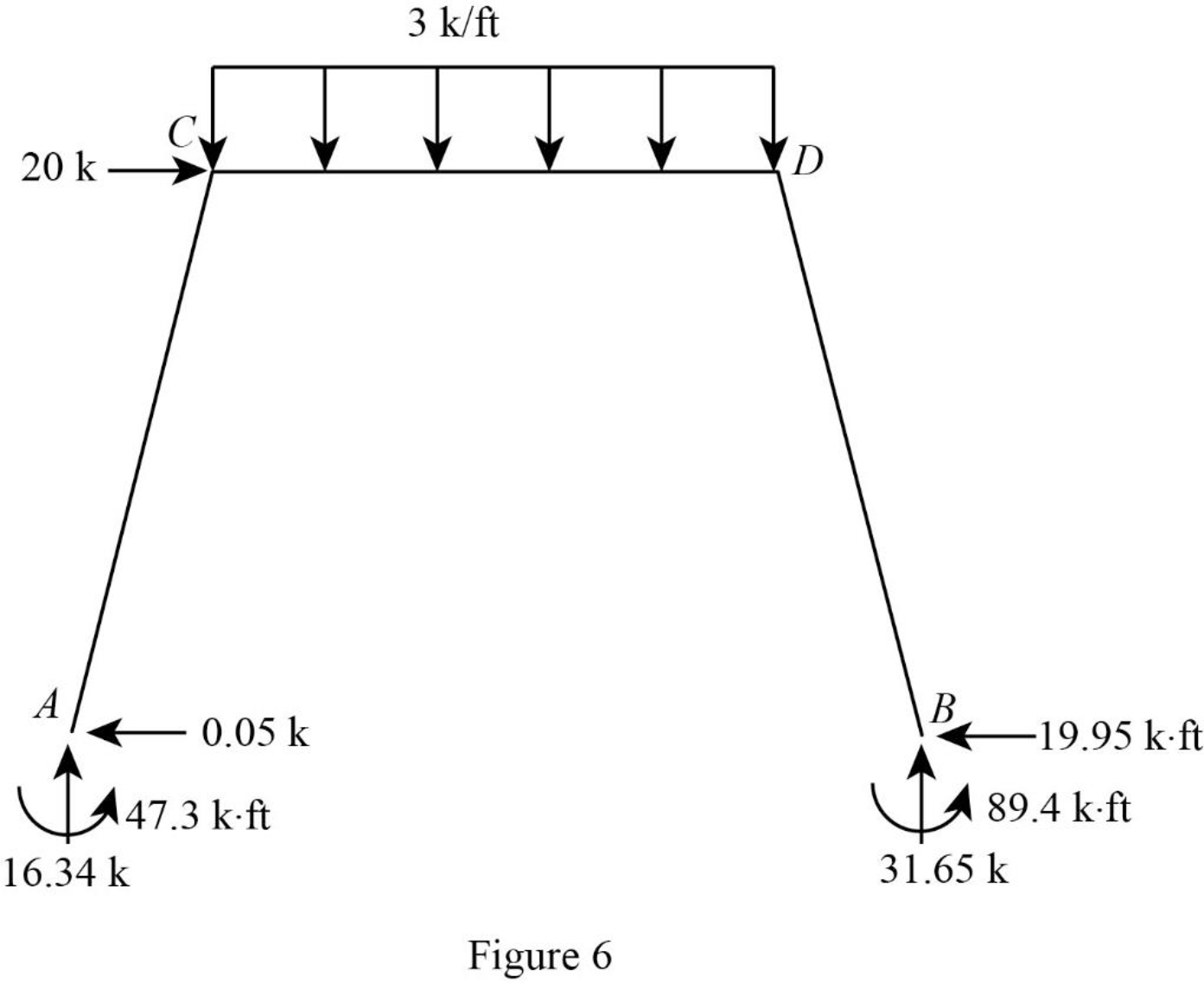
Consider the entire frame.
Calculate the horizontal reaction at the joint B by considering the horizontal equilibrium.
Show the reactions of the frame as in Figure 6.
Want to see more full solutions like this?
Chapter 16 Solutions
Structural Analysis, SI Edition


- Please answer the two questions in detail and as best as you can. Please ensure it is 100% done by human, please do not use AI or chatgpt.arrow_forwardPlease answer the two questions in detail and as best as you can. Please ensure it is 100% done by human, please do not use AI or chatgpt.arrow_forwardPlease answer the two questions in detail and as best as you can. Please ensure it is 100% done by human, please do not use AI or chatgpt.arrow_forward
- What is the value of the influence line for the bending moment around B at B for the beam shown? Determine the influence line ordinates at 3-m intervals. Select the reaction at support C to be the redundant. A a. 1.875 kN 6 m b. 0.688 kN c. 2.25 kN > d. 0.313 KN B -12 m- El = constant Carrow_forwardH.W: An activated sludge process operates under the following data: Q=0.21 m³/s, S.- 250 mg/l, S-6.2 mg/l, MLVSS (X) = 3500 mg/1, 0= 10 days Return sludge concentration (X)= 10000 mg/l, Y=0.5, K₁ =0.06 d', volatile super solid represent 80% of SS, Find: 1- Treatment efficiency 2- Reactor volume 3- Qwa (sludge wasted from areation tank) 4- Qur (sludge wasted from recirculation tank) 5- Quantity of sludge wasted/day 6- Recirculated ratio V.X VX Qwa Qwr= Qwr-Xr 0Xarrow_forwardFor the beam shown, where should a uniformly distributed downward live load, wl, be placed to cause the maximum upward reaction at support A? (D, E, and F are the supports, from left to right, to the right of C.) B C a. From A to B and D to E b. From A to D and E to F c. From B to D and E to F ☑ d. From B to C and D to E L Larrow_forward
- Question 1 1. A solid shaft of 1.55 m is used as a tractor propeller (prop) shaft. The shaft twists through 1.8 while rotating at 900 rpm. The diameter of the shaft is 60 mm and the modulus of rigidity is 85 GPa. Calculate 1.1 The maximum shear stress in the shaft 1.2 The power transmitted by the shaft. 2. The tractor has undergone minor modifications to increase the transmitted power by 20%. The solid shaft is replaced by a lighter hollow shaft of the same material, with a dimeter ratio of 2:1. Calculate the suitable dimeters of the hollow shaft.arrow_forwardUse Area Moment Method of Beam Deflectionsarrow_forwardDetermine rotations at all the nodes of the beam and reactions at the supports. Assume support 1 and 3 are roller and support 2 is pinned, L1=1.25m, L2=3.75m and w=60kN/m. Please show all working and FBD's where relevant.arrow_forward
