
Electronics Fundamentals: Circuits, Devices & Applications
8th Edition
ISBN: 9780135072950
Author: Thomas L. Floyd, David Buchla
Publisher: Prentice Hall
expand_more
expand_more
format_list_bulleted
Videos
Textbook Question
Chapter 16, Problem 30P
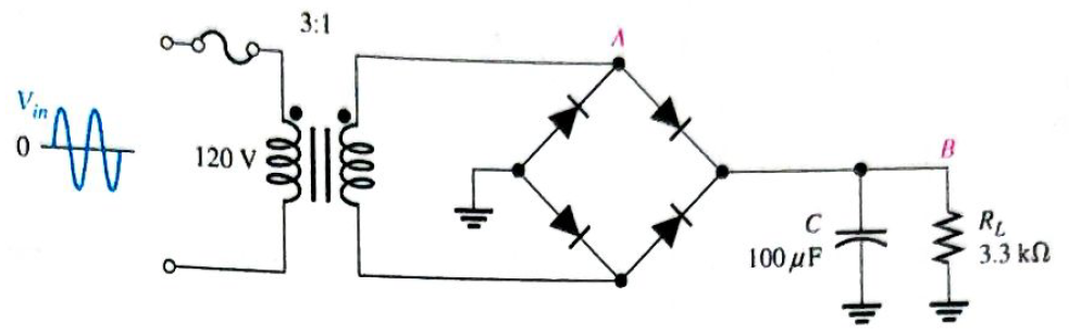
Refer to Figure 16-80 and draw the waveforms
Expert Solution & Answer
Want to see the full answer?
Check out a sample textbook solution
Students have asked these similar questions
Can you rewrite the solution because it is
unclear?
Q2
AM
①(+) = 8 (1+0.5 cos 1000πt +0.5 ros 2000kt)
$4+) = 45
=
*cos 10000 πt.
8 cos wat + 4 cosat + 4 cos Wat coswet.
j1000016
+4e
-j10000πt j11000Rt
j gooort -j 9000 πt
+
e
+e
j sooort
te
+e
J11000 t
+ e
te
j 12000rt.
-J12000 kt
+ с
= 8th S(W- 100007) + 8 IS (W-10000)
<&(w) =
USB
-5-5
-4-5-4
b) Pc 2² = 64
PSB =
42
+ 4
2
Pt Pc+ PSB =
y = Pe
c) Puss =
PLSB =
= 32
4² = 8 w
32+ 8 =
× 100% = 140
(1)³×2×2
31
= 20%
x 2 = 3w
302
USB
4.5 5 5.6 6
ms Ac = 4 mi
= 0.5
mz Ac = 4
५
M2
=
=0.5
A. Draw the waveform for the following binary sequence using Bipolar RZ, Bipolar NRZ, and
Manchester code.
Data sequence= (00110100)
B. In a binary PCM system, the output signal-to-quantization ratio is to be hold to a minimum of
50 dB. If the message is a single tone with fm-5 kHz. Determine:
1) The number of required levels, and the corresponding output signal-to-quantizing noise ratio.
2) Minimum required system bandwidth.
Find Io using Mesh analysis
Chapter 16 Solutions
Electronics Fundamentals: Circuits, Devices & Applications
Ch. 16 - Silicon can be doped with a trivalent material...Ch. 16 - The minority carriers in an n-type material are...Ch. 16 - Before a diode fully conducts, the bias must...Ch. 16 - When forward bias is applied to a diode, the...Ch. 16 - The output frequency from a full-wave rectifier is...Ch. 16 - The peak output voltage of a full-wave bridge...Ch. 16 - If one diode is open in a bridge rectifier, the...Ch. 16 - Line regulation specifies how much change occurs...Ch. 16 - Normally, zener diodes, varactor diodes, and...Ch. 16 - Prob. 10TFQ
Ch. 16 - Â Atoms within a semiconductor crystal arc held...Ch. 16 - Free electrons exist in the valence band...Ch. 16 - Prob. 3STCh. 16 - The process of adding impurity atoms to a pure...Ch. 16 - Prob. 5STCh. 16 - The majority carriers in an n-type semiconductor...Ch. 16 - The pn junction is found in diodes silicon all...Ch. 16 - Prob. 8STCh. 16 - A fixed dc voltage that sets the operating...Ch. 16 - Prob. 10STCh. 16 - When a diode is forward-biased, it is blocking...Ch. 16 - Prob. 12STCh. 16 - The process of converting ac to pulsating dc is...Ch. 16 - Prob. 14STCh. 16 - The number of diodes used in a half-wave rectifier...Ch. 16 - If a 75 V peak sine wave is applied to a half-wave...Ch. 16 - The output frequency of a full-wave rectifier with...Ch. 16 - Two types of full-wave rectifier are single diode...Ch. 16 - When a diode in a center-tapped rectifier opens,...Ch. 16 - During the positive half-cycle of the input...Ch. 16 - The process of changing a half-wave or a full-wave...Ch. 16 - Prob. 22STCh. 16 - The zener diode is designed to operate in zener...Ch. 16 - Zener diodes are sometimes used as current...Ch. 16 - Varactor diodes are used as variable resistors...Ch. 16 - Prob. 26STCh. 16 - In a photodiode, light produces reverse current...Ch. 16 - List two semiconductive materials.Ch. 16 - How many valence electrons do semiconductors have?Ch. 16 - In a silicon crystal, how many covalent bonds does...Ch. 16 - What happens when heat is added to silicon?Ch. 16 - Name the two energy levels at which current is...Ch. 16 - Describe the process of doping and explain how it...Ch. 16 - What type of impurity is antimony? What type of...Ch. 16 - Explain what a hole is.Ch. 16 - What is recombination?Ch. 16 - How is the electric field across the pn junction...Ch. 16 - Because of its barrier potential, can a diode be...Ch. 16 - To forward-bias a diode, to which region must the...Ch. 16 - Prob. 13PCh. 16 - Explain how to generate the forward-bias portion...Ch. 16 - What would cause the barrier potential to decrease...Ch. 16 - Determine whether each diode in Figure 16-74 is...Ch. 16 - Determine the voltage across each diode in Figure...Ch. 16 - Examine the meter indications in each circuit of...Ch. 16 - Determine the voltage with respect to ground at...Ch. 16 - Calculate the average value of a half-wave...Ch. 16 - Prob. 21PCh. 16 - Can a diode with a PIV rating of 50 V be used in...Ch. 16 - Prob. 23PCh. 16 - Calculate the average value of a full-wave...Ch. 16 - Consider the circuit in Figure 16-79. What type of...Ch. 16 - Calculate the peak voltage rating of each half of...Ch. 16 - Prob. 27PCh. 16 - Prob. 28PCh. 16 - The ideal dc output voltage of a capacitor-input...Ch. 16 - Refer to Figure 16-80 and draw the waveforms VA...Ch. 16 - A certain voltage regulator has a no-load output...Ch. 16 - Prob. 32PCh. 16 - Prob. 33PCh. 16 - The VZ of a given zener diode changes 38 mV for a...Ch. 16 - Figure 16-81 is a curve of reverse voltage versus...Ch. 16 - Refer to Figure 16-81 and determine the value of...Ch. 16 - When the switch in Figure 16-82 is closed, will...Ch. 16 - Prob. 38PCh. 16 - From the meter readings in Figure 16-83, determine...Ch. 16 - Each part of Figure 16-84 shows oscilloscope...Ch. 16 - For each set of measured voltages at nodes 1 and 2...Ch. 16 - Determine the most likely failure in the circuit...Ch. 16 - Prob. 43PCh. 16 - Prob. 44PCh. 16 - Prob. 45PCh. 16 - Prob. 46PCh. 16 - Open file P16-47 and determine if there is a...Ch. 16 - Open file P16-48 and determine if there is a...Ch. 16 - Open file P16-49 and determine if there is a...Ch. 16 - Open file P16-50 and determine if there is a...Ch. 16 - Prob. 51PCh. 16 - Open file P16-52 and determine if there is a...
Knowledge Booster


Learn more about
Need a deep-dive on the concept behind this application? Look no further. Learn more about this topic, electrical-engineering and related others by exploring similar questions and additional content below.Similar questions
- FM station of 100 MHz carrier frequency modulated by a 20 kHz sinusoid with an amplitude of 10 volt, so that the peak frequency deviation is 25 kHz determine: 1) The BW of the FM signal. 2) The approximated BW if the modulating signal amplitude is increased to 50 volt. 3) The approximated BW if the modulating signal frequency is increased by 70%. 4) The amplitude of the modulating signal if the BW is 65 kHz.arrow_forwardAn FDM is used to multiplex two groups of signals using AM-SSB, the first group contains 25 speech signals, each has maximum frequency of 4 kHz, the second group contains 15 music signals, each has maximum frequency of 10 kHz. A guard bandwidth of 500 Hz is used bety each two signals and before the first one. 1. Find the BWmultiplexing 2. Find the BWtransmission if the multiplexing signal is modulated using AM-DSB-LC.arrow_forwardAn FM signal with 75 kHz deviation, has an input signal-to-noise ratio of 18 dB, with a modulating frequency of 15 kHz. 1) Find SNRO at demodulator o/p. 2) Find SNRO at demodulator o/p if AM is used with m=0.3. 3) Compare the performance in case 1) and 2).. Hint: for single tone AM-DSB-LC, SNR₁ = (2m²) (4)arrow_forward
- Find Va and Vb using Nodal analysisarrow_forward4. A battery operated sensor transmits to a receiver that is plugged in to a power outlet. The device is continuously operated. The battery is a 3.6 V coin-cell battery with a 245mAHr capacity. The application requires a bit rate of 36 Mbps and an error rate of less than 10^-3. The channel has a center frequency of 2.4 GHz, a bandwidth of 10 MHz and a noise power spectral density of 10^-14 W/Hz. The maximum distance is 36 meters and the losses in the channel attenuates the signal by 0.25 dB/meter. Your company has two families of chips that you can use. An M-ary ASK and an M-ary QAM chip. The have very different power requirements as shown in the table below. The total current for the system is the current required to achieve the desired Eb/No PLUS the current identified below: Hokies PSK Chip Set Operating Current NOT Including the required Eb/No for the application Hokies QAM Chip Set Operating Current NOT Including the required Eb/No for the application Chip ID M-ary Voltage (volts)…arrow_forwardUsing the 802.11a specifications given below, in Matlab (or similar tool) create the time domain signal for one OFDM symbol using QPSK modulation. See attached plot for the QPSK constellation. Your results should include the power measure in the time and frequency domain and comment on those results. BW 802.11a OFDM PHY Parameters 20 MHZ OBW Subcarrer Spacing Information Rate Modulation Coding Rate Total Subcarriers Data Subcarriers Pilot Subcarriers DC Subcarrier 16.6 MHZ 312.5 Khz (20MHz/64 Pt FFT) 6/9/12/18/24/36/48/54 Mbits/s BPSK, QPSK, 16QAM, 64QAM 1/2, 2/3, 3/4 52 (Freq Index -26 to +26) 48 4 (-21, -7, +7, +21) *Always BPSK Null (0 subcarrier) 52 subarriers -7 (48 Data, 4 Pilot (BPSK), 1 Null) -26 -21 0 7 21 +26 14 One Subcarrier 1 OFDM symbol 1 OFDM Burst -OBW 16.6 MHz BW 20 MHZ 1 constellation point = 52 subcarriers = one or more OFDM symbols 802.11a OFDM Physical Parameters Show signal at this point x bits do Serial Data d₁ S₁ Serial-to- Input Signal Parallel Converter IFFT…arrow_forward
- Find Vb and Va using Mesh analysisarrow_forward1. The communication channel bandwidth is 25 MHz centered at 1GHz and has a noise power spectral density of 10^-9 W/Hz. The channel loss between the transmitter and receiver is 25dB. The application requires a bit rate of 200Mbps and BER of less than 10^-4. Excluding Mary FSK, Determine the minimum transmit power required.arrow_forward2. An existing system uses noncoherent BASK. The application requires a BER of <10^-5. The current transmit power is 25 Watts. If the system changes to a coherent BPSK modulation scheme, what is the new transmit power required to deliver the same BER?arrow_forward
arrow_back_ios
SEE MORE QUESTIONS
arrow_forward_ios
Recommended textbooks for you
 Introductory Circuit Analysis (13th Edition)Electrical EngineeringISBN:9780133923605Author:Robert L. BoylestadPublisher:PEARSON
 Delmar's Standard Textbook Of ElectricityElectrical EngineeringISBN:9781337900348Author:Stephen L. HermanPublisher:Cengage Learning
 Programmable Logic ControllersElectrical EngineeringISBN:9780073373843Author:Frank D. PetruzellaPublisher:McGraw-Hill Education
 Fundamentals of Electric CircuitsElectrical EngineeringISBN:9780078028229Author:Charles K Alexander, Matthew SadikuPublisher:McGraw-Hill Education
 Electric Circuits. (11th Edition)Electrical EngineeringISBN:9780134746968Author:James W. Nilsson, Susan RiedelPublisher:PEARSON
 Engineering ElectromagneticsElectrical EngineeringISBN:9780078028151Author:Hayt, William H. (william Hart), Jr, BUCK, John A.Publisher:Mcgraw-hill Education,
Introductory Circuit Analysis (13th Edition)
Electrical Engineering
ISBN:9780133923605
Author:Robert L. Boylestad
Publisher:PEARSON
Delmar's Standard Textbook Of Electricity
Electrical Engineering
ISBN:9781337900348
Author:Stephen L. Herman
Publisher:Cengage Learning
Programmable Logic Controllers
Electrical Engineering
ISBN:9780073373843
Author:Frank D. Petruzella
Publisher:McGraw-Hill Education
Fundamentals of Electric Circuits
Electrical Engineering
ISBN:9780078028229
Author:Charles K Alexander, Matthew Sadiku
Publisher:McGraw-Hill Education
Electric Circuits. (11th Edition)
Electrical Engineering
ISBN:9780134746968
Author:James W. Nilsson, Susan Riedel
Publisher:PEARSON
Engineering Electromagnetics
Electrical Engineering
ISBN:9780078028151
Author:Hayt, William H. (william Hart), Jr, BUCK, John A.
Publisher:Mcgraw-hill Education,
Power Inverters Explained - How do they work working principle IGBT; Author: The Engineering Mindset;https://www.youtube.com/watch?v=iIqhAX0I7lI;License: Standard Youtube License