
Concept explainers
Videos
(a)
The position of first bright fringe.
(a)
Answer to Problem 2SP
The position of first bright fringe is 17.1 mm away from the center at each side.
Explanation of Solution
Given info:
Write an expression for condition of maxima.
Here,
Substitute
Thus, the position of first bright fringe is 17.1 mm away from the center at each side.
Conclusion:
The position of first bright fringe is 17.1 mm away from the center at each side.
(b)
The position of second bright fringe.
(b)
Answer to Problem 2SP
The position of second bright fringe is 34.3 mm away from the center at each side.
Explanation of Solution
Given info:
Wavelength of the light is
Write an expression for condition of maxima.
Here,
Substitute
Thus, the position of second bright fringe is 34.3 mm away from the center at each side.
Conclusion:
The position of second bright fringe is 34.3 mm away from the center at each side.
(c)
The position of first dark bright fringe.
(c)
Answer to Problem 2SP
The position of first dark fringe is 25.7 mm away from the center at each side.
Explanation of Solution
Given info:
Wavelength of the light is
Write an expression for condition of minima.
Here,
Substitute
Thus, the position of first dark fringe is 25.7 mm away from the center at each side.
Conclusion:
The position of first dark fringe is 25.7 mm away from the center at each side.
(d)
Sketch the diffraction pattern and mark the position of the fringes.
(d)
Answer to Problem 2SP
The diffraction pattern is given in figure 1.
Explanation of Solution
Following figure gives the diffraction pattern.
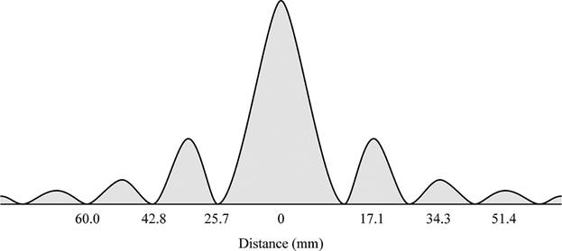
Figure 1
Here, the first, second and third order bright fringes will appear at distance of 17.1 mm, 34.3 mm and 51.4 mm from center respectively at each side of the central maxima. The dark fringes of order 1, 2 and 3 will form distances 25.7 mm, 42.8 mm and 60.0 mm respectively.
Conclusion:
The diffraction pattern is given in figure 1.
Want to see more full solutions like this?
Chapter 16 Solutions
Physics of Everyday Phenomena


- Suppose there are two transformers between your house and the high-voltage transmission line that distributes the power. In addition, assume your house is the only one using electric power. At a substation the primary of a step-down transformer (turns ratio = 1:23) receives the voltage from the high-voltage transmission line. Because of your usage, a current of 51.1 mA exists in the primary of the transformer. The secondary is connected to the primary of another step-down transformer (turns ratio = 1:36) somewhere near your house, perhaps up on a telephone pole. The secondary of this transformer delivers a 240-V emf to your house. How much power is your house using? Remember that the current and voltage given in this problem are rms values.arrow_forwardThe human eye is most sensitive to light having a frequency of about 5.5 × 10¹⁴ Hz, which is in the yellow-green region of the electromagnetic spectrum. How many wavelengths of this light can fit across a distance of 2.2 cm?arrow_forwardA one-dimensional harmonic oscillator of mass m and angular frequency w is in a heat bath of temperature T. What is the root mean square of the displacement of the oscillator? (In the expressions below k is the Boltzmann constant.) Select one: ○ (KT/mw²)1/2 ○ (KT/mw²)-1/2 ○ kT/w O (KT/mw²) 1/2In(2)arrow_forward
- Two polarizers are placed on top of each other so that their transmission axes coincide. If unpolarized light falls on the system, the transmitted intensity is lo. What is the transmitted intensity if one of the polarizers is rotated by 30 degrees? Select one: ○ 10/4 ○ 0.866 lo ○ 310/4 01/2 10/2arrow_forwardBefore attempting this problem, review Conceptual Example 7. The intensity of the light that reaches the photocell in the drawing is 160 W/m², when 0 = 18°. What would be the intensity reaching the photocell if the analyzer were removed from the setup, everything else remaining the same? Light Photocell Polarizer Insert Analyzerarrow_forwardThe lifetime of a muon in its rest frame is 2.2 microseconds. What is the lifetime of the muon measured in the laboratory frame, where the muon's kinetic energy is 53 MeV? It is known that the rest energy of the muon is 106 MeV. Select one: O 4.4 microseconds O 6.6 microseconds O 3.3 microseconds O 1.1 microsecondsarrow_forward
- The Lagrangian of a particle performing harmonic oscil- lations is written in the form L = ax² - Bx² - yx, where a, and are constants. What is the angular frequency of oscillations? A) √2/a B) √(+2a)/B C) √√Ba D) B/αarrow_forwardThe mean temperature of the Earth is T=287 K. What would the new mean temperature T' be if the mean distance between the Earth and the Sun was increased by 2%? Select one: ○ 293 K O 281 K ○ 273 K 284 Karrow_forwardTwo concentric current-carrying wire loops of radius 3 cm and 9 cm lie in the same plane. The currents in the loops flow in the same direction and are equal in magnitude. The magnetic field at the common center of the loops is 50 mT. What would be the value of magnetic field at the center if the direction of the two currents was opposite to each other (but their value is kept constant)? Select one: ○ 20 mT ○ 10 mT O 15 mT ○ 25 mTarrow_forward
- An ideal coil of inductivity 50 mH is connected in series with a resistor of 50 ohm. This system is connected to a 4.5 V battery for a long time. What is the current in the circuit? Select one: O 45 mA ○ 90 mA 00 mA O 150 mAarrow_forwardThere are two thin-walled spherical shells made from the same material, the radius of the smaller shell is half of the radius of the larger one. The thickness of the walls is the same. Denote the moment of inertia (with respect to the center) of the larger shell by I₁, and that of the smaller one by 12. What is the ratio I₁/12? Select one: ○ 8 O 16 O 4 ○ 32arrow_forwardA swimming pool has dimensions 20.0 m X 20.0 m and a flat bottom. The pool is filled to a depth of 3.00 m with fresh water. By what force does the water push each of the sidewalls? Density of water is 1000 kg/m³. Select one: ○ ~ 900 KN о ~ 2 ~ 1800 kN 600 kN 1500 kNarrow_forward
 College PhysicsPhysicsISBN:9781938168000Author:Paul Peter Urone, Roger HinrichsPublisher:OpenStax College
 College PhysicsPhysicsISBN:9781305952300Author:Raymond A. Serway, Chris VuillePublisher:Cengage Learning
 Principles of Physics: A Calculus-Based TextPhysicsISBN:9781133104261Author:Raymond A. Serway, John W. JewettPublisher:Cengage Learning
 Physics for Scientists and Engineers with Modern ...PhysicsISBN:9781337553292Author:Raymond A. Serway, John W. JewettPublisher:Cengage Learning
 College PhysicsPhysicsISBN:9781285737027Author:Raymond A. Serway, Chris VuillePublisher:Cengage Learning
 Physics for Scientists and Engineers, Technology ...PhysicsISBN:9781305116399Author:Raymond A. Serway, John W. JewettPublisher:Cengage Learning