
Concept explainers
Videos
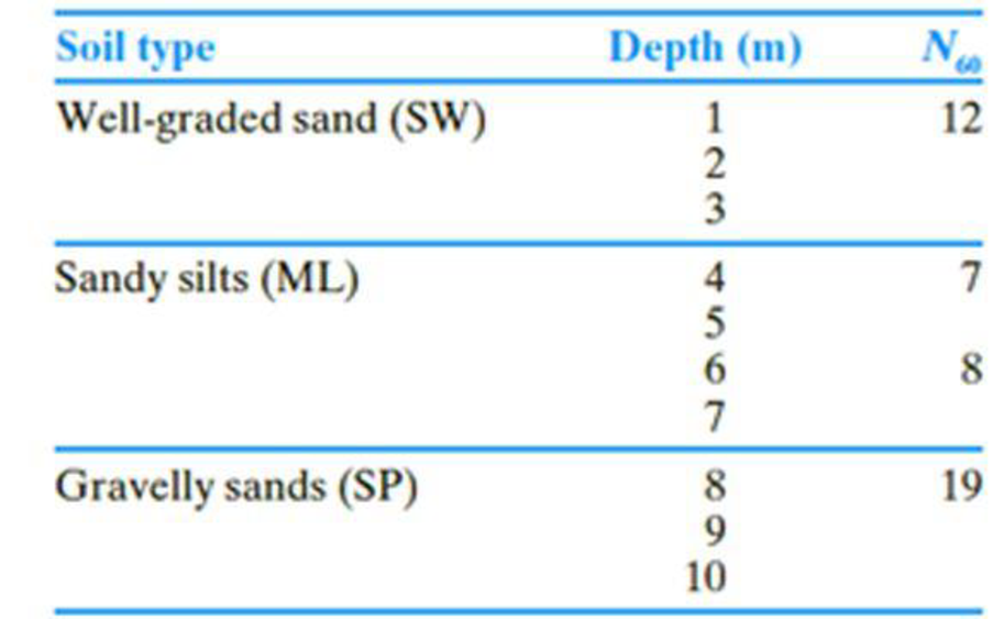
The following table shows the boring log at a site where a multi-story shopping center would be constructed. Soil classification and the standard penetration number, N60, are provided in the boring log. All columns of the building are supported by square footings which must be placed at a depth of 1.5 m. Additionally, the settlement (elastic) of each footing must be restricted to 20 mm. Since the column loads at different location can vary, a design chart is helpful for quick estimation of footing size required to support a given load.
- a. Prepare a chart by plotting the variation of maximum allowable column loads with footing sizes, B = 1 m, 1.5 m, 2 m, and 3 m. Use a factor of safety of 3.
- b. If the gross column load from the structure is 250 kN, how would you use this chart to select a footing size?
- c. What would be the design footing size for the column in Part (b) if you use Terzaghi’s bearing capacity equation? For the well graded sand, assume that ϕ′ = 33°. Use Fs = 3.
- d. Compare and discuss the differences in footing sizes obtained in Parts b and c.
(a)
Plot the variation of maximum allowable column loads with size of footings to prepare a chart.
Explanation of Solution
Given information:
The location of depth of footing
The given size of the footing B is 1 m, 1.5 m, 2 m, and 3 m.
The settlement of each footing
The given factor of safety
Calculation:
For B value is 1 m:
Determine the depth factor using the relation.
Substitute 1.5 m for
The
The field standard penetration number
Determine the depth of foundation for the field standard penetration number gets averaged.
Substitute 1.5 m for
Determine the averaged
Here,
Substitute 12 for
Determine the net allowable bearing capacity of the soil
Substitute 10 for
Determine the maximum allowable column load
Substitute
For B value is 1.5 m:
Determine the depth factor using the relation.
Substitute 1.5 m for
The field standard penetration number
Determine the depth of foundation for the field standard penetration number gets averaged.
Substitute 1.5 m for
Determine the averaged
Here,
Substitute 7 for
Determine the net allowable bearing capacity of the soil
Substitute 8 for
Determine the maximum allowable column load
Substitute
For B value is 2 m:
Determine the depth factor using the relation.
Substitute 1.5 m for
The field standard penetration number
Determine the depth of foundation for the field standard penetration number gets averaged.
Substitute 1.5 m for
Determine the averaged
Substitute 12 for
Determine the net allowable bearing capacity of the soil
Substitute 9 for
Determine the maximum allowable column load
Substitute
For B value is 3 m:
Determine the depth factor using the relation.
Substitute 1.5 m for
The field standard penetration number
Determine the depth of foundation for the field standard penetration number gets averaged.
Substitute 1.5 m for
Determine the averaged
Here,
Substitute 12 for
Determine the net allowable bearing capacity of the soil
Substitute 12 for
Determine the maximum allowable column load
Substitute
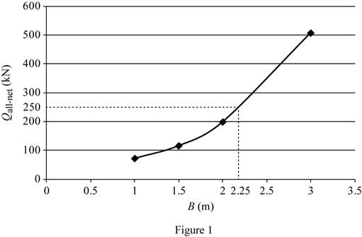
Summarize the calculated values as in Table (1).
| Width B (m) | Column load (kN) |
| 1 | 71 |
| 1.5 | 115 |
| 2 | 198 |
| 3 | 507.5 |
Plot the graph between the size of the footing and the column load as in Figure (1).
(b)
Find the footing size for the given gross column load of 250 kN.
Answer to Problem 16.1CTP
The footing size for the given gross column load of 250 kN is
Explanation of Solution
Given information:
The location of depth of footing
The given size of the footing B is 1 m, 1.5 m, 2 m, and 3 m.
The settlement of each footing
The given factor of safety
Calculation:
Refer Figure (1).
The size of the footing is 2.25 m for the gross column load of 250 kN.
Therefore, the footing size for the given gross column load of 250 kN is
(c)
Find the design column load for the footing size of 2.25 m using the Terzaghi’s bearing capacity equation.
Answer to Problem 16.1CTP
The design column load for the footing size of 2.25 m using the Terzaghi’s bearing capacity equation is
Explanation of Solution
Given information:
The value of cohesion
The soil friction angle
The location of depth of footing base
The width of the footing B is 2.25 m.
The given factor of safety
Calculation:
Determine the net ultimate bearing capacity of the soil
Here,
Take the unit weight of the soil
Refer Table 16.1, “Terzaghi’s bearing-capacity factors–
Take the
Substitute
Determine the net allowable bearing capacity
Substitute
Therefore, the design column load for the footing size of 2.25 m using the Terzaghi’s bearing capacity equation is
(d)
Compare and discuss the differences in footing sizes obtained in parts (b) and (c).
Explanation of Solution
Given information:
The soil friction angle
The location of depth of footing base
The width of the footing B is 2.25 m.
The given factor of safety
Calculation:
The net allowable column load obtained by using Terzaghi’s bearing capacity equation (2,173 kN) is significantly higher than the method based on the
Want to see more full solutions like this?
Chapter 16 Solutions
Bundle: Principles Of Geotechnical Engineering, Loose-leaf Version, 9th + Mindtap Engineering, 1 Term (6 Months) Printed Access Card


- Please explain step by step and show all the formula usedarrow_forwardBy using the yield line theory, determine the moment (m) for an isotropic reinforced concrete two- way slab shown in figure under a uniformly distributed load. Using moment method 5 2 7.0m 1 A I c.g. * B c.g 5 2 B c. g. ㄨˋ A A 2.5 2.0 2.5 5.0marrow_forwardPlease explain step by step and include any formula usedarrow_forward
- Explain step by step, show what formulas usedarrow_forward2 1d/T₁₂ = 1/2 n First impulse E ("œw / ])÷(1) '7 J-1 -1- -2+ 0 0.5 1 1.5 2arrow_forwardBars AD and CE (E=105 GPa, a = 20.9×10⁻⁶ °C) support a rigid bar ABC carrying a linearly increasing distributed load as shown. The temperature of Bar CE was then raised by 40°C while the temperature of Bar AD remained unchanged. If Bar AD has a cross-sectional area of 200 mm² while CE has 150 mm², determine the following: the normal force in bar AD, the normal force in bar CE, and the vertical displacement at Point A. D 0.4 m -0.8 m A -0.4 m- B -0.8 m- E 0.8 m C 18 kN/marrow_forward
- Draw the updated network. Calculate the new project completion date. Check if there are changes to the completion date and/or to the critical path. Mention the causes for such changes, if any. New network based on the new information received after 15 days (Correct calculations, professionally done). Mention if critical path changes or extended. Write causes for change in critical path or extension in the critical path.arrow_forwardThe single degree of freedom system shown in Figure 3 is at its undeformed position. The SDOF system consists of a rigid beam that is massless. The rigid beam has a pinned (i.e., zero moment) connection to the wall (left end) and it supports a mass m on its right end. The rigid beam is supported by two springs. Both springs have the same stiffness k. The first spring is located at distance L/4 from the left support, where L is the length of the rigid beam. The second spring is located at distance L from the left support.arrow_forwardFor the system shown in Figure 2, u(t) and y(t) denote the absolute displacements of Building A and Building B, respectively. The two buildings are connected using a linear viscous damper with damping coefficient c. Due to construction activity, the floor mass of Building B was estimated that vibrates with harmonic displacement that is described by the following function: y(t) = yocos(2πft). Figure 2: Single-degree-of-freedom system in Problem 2. Please compute the following related to Building A: (a) Derive the equation of motion of the mass m. (20 points) (b) Find the expression of the amplitude of the steady-state displacement of the mass m. (10 pointsarrow_forward
 Principles of Geotechnical Engineering (MindTap C...Civil EngineeringISBN:9781305970939Author:Braja M. Das, Khaled SobhanPublisher:Cengage Learning
 Principles of Foundation Engineering (MindTap Cou...Civil EngineeringISBN:9781337705028Author:Braja M. Das, Nagaratnam SivakuganPublisher:Cengage Learning
 Fundamentals of Geotechnical Engineering (MindTap...Civil EngineeringISBN:9781305635180Author:Braja M. Das, Nagaratnam SivakuganPublisher:Cengage Learning
 Principles of Foundation Engineering (MindTap Cou...Civil EngineeringISBN:9781305081550Author:Braja M. DasPublisher:Cengage Learning
 Construction Materials, Methods and Techniques (M...Civil EngineeringISBN:9781305086272Author:William P. Spence, Eva KultermannPublisher:Cengage Learning