
Concept explainers
Videos
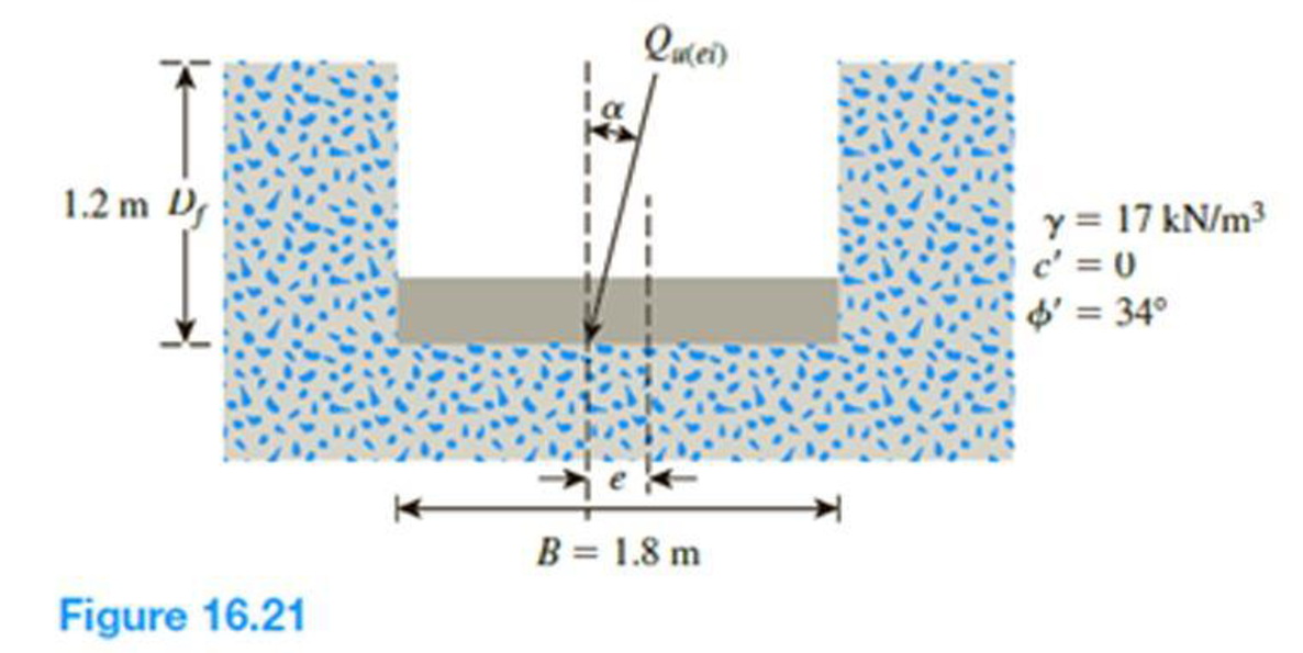
Figure 16.21 shows a continuous foundation with a width of 1.8 m constructed at a depth of 1.2 m in a granular soil. The footing is subjected to an eccentrically inclined loading with e = 0.3 m, and α = 10°. Determine the gross ultimate load, Qu(ei), that the footing can support using:
- a. Meyerhof (1963) method [Eq. (16.52)]
- b. Saran and Agarwal (1991) method [Eq. (16.53)]
- c. Patra et al. (2012) reduction factor method [Eq. (16.54)]
(a)
The gross ultimate load
Answer to Problem 16.19P
The gross ultimate load
Explanation of Solution
Given information:
The unit weight of the soil
The value of cohesion
The soil friction angle
The location of depth of footing base
The width of the footing B is 1.8 m.
The value of eccentricity e is 0.3 m.
The inclined angle
Calculation:
Determine the effective width of the footing using the relation.
Substitute 1.8 m for B and 0.3 for e.
For the continuous foundation, all shape factors are equal to one
Determine the depth factor
Substitute 1.2 m for
Determine the depth factor
Substitute
Determine the inclination factor
Substitute
Determine the inclination factor
Substitute
Determine the ultimate bearing capacity of the soil
Here,
Refer Table 16.2, “Bearing-capacity factors
For
The values of
Substitute 0 for
Determine the gross ultimate load
Substitute
Therefore, the gross ultimate load
(b)
The gross ultimate load
Answer to Problem 16.19P
The gross ultimate load
Explanation of Solution
Given information:
The unit weight of the soil
The value of cohesion
The soil friction angle
The location of depth of footing base
The width of the footing B is 1.8 m.
The value of eccentricity e is 0.3 m.
The inclined angle
Calculation:
Determine the ratio of
Substitute 0.3 for e and 1.8 m for B.
Determine the gross ultimate load
Here,
Refer Figure 16.14, “Variation of
Take the
Refer Figure 16.15, “Variation of
Take the
Refer Figure 16.16, “Variation of
Take the
Substitute 0 for
Therefore, the gross ultimate load
(c)
The gross ultimate load
Answer to Problem 16.19P
The gross ultimate load
Explanation of Solution
Given information:
The unit weight of the soil
The value of cohesion
The soil friction angle
The location of depth of footing base
The width of the footing B is 1.8 m.
The value of eccentricity e is 0.3 m.
The inclined angle
Calculation:
For the continuous foundation, all shape factors are equal to one
Determine the depth factor
Substitute 1.2 m for
Determine the depth factor
Substitute
Determine the ultimate bearing capacity of the soil
Refer Table 16.2, “Bearing-capacity factors
Take the
Substitute 0 for
Determine the gross ultimate load
Substitute 1.8 m for B,
Therefore, the gross ultimate load
Want to see more full solutions like this?
Chapter 16 Solutions
Principles of Geotechnical Engineering (MindTap Course List)


- Please explain step by step and show all the formula usedarrow_forwardBy using the yield line theory, determine the moment (m) for an isotropic reinforced concrete two- way slab shown in figure under a uniformly distributed load. Using moment method 5 2 7.0m 1 A I c.g. * B c.g 5 2 B c. g. ㄨˋ A A 2.5 2.0 2.5 5.0marrow_forwardPlease explain step by step and include any formula usedarrow_forward
- Explain step by step, show what formulas usedarrow_forward2 1d/T₁₂ = 1/2 n First impulse E ("œw / ])÷(1) '7 J-1 -1- -2+ 0 0.5 1 1.5 2arrow_forwardBars AD and CE (E=105 GPa, a = 20.9×10⁻⁶ °C) support a rigid bar ABC carrying a linearly increasing distributed load as shown. The temperature of Bar CE was then raised by 40°C while the temperature of Bar AD remained unchanged. If Bar AD has a cross-sectional area of 200 mm² while CE has 150 mm², determine the following: the normal force in bar AD, the normal force in bar CE, and the vertical displacement at Point A. D 0.4 m -0.8 m A -0.4 m- B -0.8 m- E 0.8 m C 18 kN/marrow_forward
- Draw the updated network. Calculate the new project completion date. Check if there are changes to the completion date and/or to the critical path. Mention the causes for such changes, if any. New network based on the new information received after 15 days (Correct calculations, professionally done). Mention if critical path changes or extended. Write causes for change in critical path or extension in the critical path.arrow_forwardThe single degree of freedom system shown in Figure 3 is at its undeformed position. The SDOF system consists of a rigid beam that is massless. The rigid beam has a pinned (i.e., zero moment) connection to the wall (left end) and it supports a mass m on its right end. The rigid beam is supported by two springs. Both springs have the same stiffness k. The first spring is located at distance L/4 from the left support, where L is the length of the rigid beam. The second spring is located at distance L from the left support.arrow_forwardFor the system shown in Figure 2, u(t) and y(t) denote the absolute displacements of Building A and Building B, respectively. The two buildings are connected using a linear viscous damper with damping coefficient c. Due to construction activity, the floor mass of Building B was estimated that vibrates with harmonic displacement that is described by the following function: y(t) = yocos(2πft). Figure 2: Single-degree-of-freedom system in Problem 2. Please compute the following related to Building A: (a) Derive the equation of motion of the mass m. (20 points) (b) Find the expression of the amplitude of the steady-state displacement of the mass m. (10 pointsarrow_forward
 Principles of Geotechnical Engineering (MindTap C...Civil EngineeringISBN:9781305970939Author:Braja M. Das, Khaled SobhanPublisher:Cengage Learning
 Principles of Foundation Engineering (MindTap Cou...Civil EngineeringISBN:9781337705028Author:Braja M. Das, Nagaratnam SivakuganPublisher:Cengage Learning
 Principles of Foundation Engineering (MindTap Cou...Civil EngineeringISBN:9781305081550Author:Braja M. DasPublisher:Cengage Learning
 Fundamentals of Geotechnical Engineering (MindTap...Civil EngineeringISBN:9781305635180Author:Braja M. Das, Nagaratnam SivakuganPublisher:Cengage Learning