
Concept explainers
Videos
(a)
The common angular acceleration of unit AB.
(a)
Answer to Problem 15.200P
The common angular acceleration of unit AB
Explanation of Solution
Given information:
The constant angular velocities of gears C and D is 30 rad/s and 20 rad/s respectively.
Calculation:
Draw the free body diagram of the planetary gear system as in Figure (1).
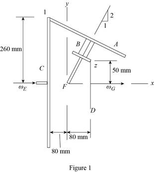
Place origin at F.
Write the relative position vector
Write the relative position vector
Determine the velocity value
Here,
Substitute
Determine the velocity value
Here,
Substitute
The motion of gear unit AB is
Determine the velocity vector
Substitute
Substitute 0 for
Equate the k component in Equation (1).
Determine the velocity vector
Substitute
Equate the k component.
Add the Equation (2) and (3).
Determine the value of
Substitute
Determine the common angular velocity of gears A and B
Substitute
Draw the free body diagram of the shaft system with FH as in Figure (2).
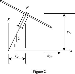
The point N is at nut, which is a part of unit AB and also is a part of shaft GH.
Write the distance of point N along x axis.
Write the relative position vector
Substitute
The nut N as a part of unit AB.
Determine the velocity vector
Substitute
The nut N as a part of shaft FH.
Determine the velocity vector
Substitute
Equate the Equations (4) and (5).
The angular velocity vector
Determine the common angular acceleration of unit AB.
Substitute
Therefore, the common angular acceleration of unit AB
(b)
The acceleration of the tooth of gear A which is in contact with gear C at point 1.
(b)
Answer to Problem 15.200P
The acceleration of the tooth of gear A which is in contact with gear C at point 1
Explanation of Solution
Given information:
The constant angular velocities of gears C and D is 30 rad/s and 20 rad/s respectively.
Calculation:
Determine the acceleration of the tooth of gear A which is in contact with gear C at point 1.
Substitute
Therefore, the acceleration of the tooth of gear A which is in contact with gear C at point 1
Want to see more full solutions like this?
Chapter 15 Solutions
Connect 1 Semester Access Card for Vector Mechanics for Engineers: Statics and Dynamics


- 6.76 A wind turbine is operating in a 12 m/s wind that has a den- sity of 1.2 kg/m³. The diameter of the turbine silhouette is 4 m. The constant-pressure (atmospheric) streamline has a diameter of 3 m upstream of the windmill and 4.5 m downstream. Assume that the velocity distributions are uniform and the air is incom- pressible. Determine the force on the wind turbine. m P = Patm 4 Vz 4m 4 m Fx. Problem 6.76arrow_forwardFor the position shown in the figure the spring is unstretched. The spring constant k, is designed such that after the system is released from rest, the speed of the mass is zero just as the 0.6 slug mass touches the floor. Find the spring constant, k and the maximum speed of block A and the location (distance above floor) where this occurs.arrow_forward||! Sign in MMB241 - Tutorial L9.pd X PDF MMB241 - Tutorial L10.pX DE MMB241 - Tutorial L11.p x PDF Lecture W12 - Work and X File C:/Users/KHULEKANI/Desktop/mmb241/MMB241%20-%20Tutorial%20L11.pdf PDE Lecture W11 - Power and X Draw Alla | Ask Copilot ++ 3 of 3 | D 6. If the 50-kg load A is hoisted by motor M so that the load has a constant velocity of 1.5 m/s, determine the power input to the motor, which operates at an efficiency € = 0.8. 1.5 m/s 2 7. The sports car has a mass of 2.3 Mg, and while it is traveling at 28 m/s the driver causes it to accelerate at 5m/s². If the drag resistance on the car due to the wind is FD= 0.3v²N, where v is the velocity in m/s, determine the power supplied to the engine at this instant. The engine has a running efficiency of P = 0.68. 8. If the jet on the dragster supplies a constant thrust of T-20 kN, determine the power generated by the jet as a function of time. Neglect drag and rolling resistance, and the loss of fuel. The dragster has a mass of 1…arrow_forward
- Q | Sign in PDE Lecture W09.pdf PDF MMB241 - Tutorial L9.pdi X PDF MMB241 - Tutorial L10.p X PDF MMB241 - Tutorial L11.p X Lecture W12-Work and X + File C:/Users/KHULEKANI/Desktop/mmb241/Lecture%20W12%20-%20Work%20and%20Energy.pdf ||! Draw | IA | a | Ask Copilot Class Work + 33 of 34 D Question 1 The engine of a 3500-N car is generating a constant power of 50 hp (horsepower) while the car is traveling up the slope with a constant speed. If the engine is operating with an efficiency of € 0.8, determine the speed of the car. Neglect drag and rolling resistance. Use g 9.81 m/s² and 1 hp = 745.7 W. 10 го Question 2 A man pushes on a 60-N crate with a force F. The force is always directed downward at an angle of 30° from the horizontal, as shown in the figure. The magnitude of the force is gradually increased until the crate begins to slide. Determine the crate's initial acceleration once it starts to move. Assume the coefficient of static friction is μ = 0.6, the coefficient of kinetic…arrow_forwardstate is Derive an expression for the volume expansivity of a substance whose equation of RT P = v-b a v(v + b)TZ where a and b are empirical constants.arrow_forwardFor a gas whose equation of state is P(v-b)=RT, the specified heat difference Cp-Cv is equal to which of the following (show all work): (a) R (b) R-b (c) R+b (d) 0 (e) R(1+v/b)arrow_forward
- of state is Derive an expression for the specific heat difference of a substance whose equation RT P = v-b a v(v + b)TZ where a and b are empirical constants.arrow_forwardTemperature may alternatively be defined as T = ди v Prove that this definition reduces the net entropy change of two constant-volume systems filled with simple compressible substances to zero as the two systems approach thermal equilibrium.arrow_forwardUsing the Maxwell relations, determine a relation for equation of state is (P-a/v²) (v−b) = RT. Os for a gas whose av Tarrow_forward
- (◉ Homework#8arrow_forwardHomework#8arrow_forwardBox A has a mass of 15 kilograms and is attached to the 20 kilogram Box B using the cord and pulley system shown. The coefficient of kinetic friction between the boxes and surface is 0.2 and the moment of inertia of the pulley is 0.5 kg * m^ 2. After 2 seconds, how far do the boxes move? A бро Barrow_forwardarrow_back_iosSEE MORE QUESTIONSarrow_forward_ios
 Elements Of ElectromagneticsMechanical EngineeringISBN:9780190698614Author:Sadiku, Matthew N. O.Publisher:Oxford University Press
 Mechanics of Materials (10th Edition)Mechanical EngineeringISBN:9780134319650Author:Russell C. HibbelerPublisher:PEARSON
 Thermodynamics: An Engineering ApproachMechanical EngineeringISBN:9781259822674Author:Yunus A. Cengel Dr., Michael A. BolesPublisher:McGraw-Hill Education
 Control Systems EngineeringMechanical EngineeringISBN:9781118170519Author:Norman S. NisePublisher:WILEY
 Mechanics of Materials (MindTap Course List)Mechanical EngineeringISBN:9781337093347Author:Barry J. Goodno, James M. GerePublisher:Cengage Learning
 Engineering Mechanics: StaticsMechanical EngineeringISBN:9781118807330Author:James L. Meriam, L. G. Kraige, J. N. BoltonPublisher:WILEY