
Concept explainers
Videos
(a)
The angular velocity and angular acceleration of the point C on the output belt.
(a)
Answer to Problem 15.23P
The angular velocity
Explanation of Solution
Given information:
The inner radius of left pulley
The outer radius of left pulley
The velocity of point A
The tangential component of acceleration of point A
The inner radius of right pulley
The outer radius of right pulley
Calculation:
Left pulley:
Determine the angular velocity of the left pulley
Substitute 2 ft/s for
Draw the free body diagram of the left pulley as in Figure (1).
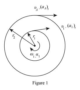
Determine the angular acceleration of the left pulley
Substitute
Intermediate belt:
Determine the velocity of the intermediate belt
Substitute 2 in. for
Determine the tangential component of acceleration of the intermediate belt
Substitute 2 in. for
Right pulley:
Draw the free body diagram of the right pulley as in Figure (2).
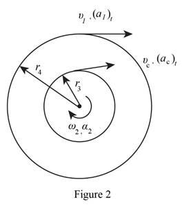
Determine the angular velocity of the right pulley
Substitute 1 ft/s for
Determine the angular acceleration of the right pulley
Substitute
Determine the velocity of point C.
Substitute 2 in. for
Determine the tangential component of acceleration of point C
Substitute 2 in. for
Therefore, the angular velocity
(b)
The acceleration of the point B on the output pulley.
(b)
Answer to Problem 15.23P
The acceleration of point B on the output pulley is
Explanation of Solution
Given information:
The inner radius of left pulley
The outer radius of left pulley
The velocity of point A
The tangential component of acceleration of point A
The inner radius of right pulley
The outer radius of right pulley
Calculation:
Determine the normal component of acceleration of point B
Substitute 4 in. for
Determine the tangential component of acceleration of point B
Substitute 4 in. for
Determine the magnitude of the total acceleration of the machine component at B.
Substitute
Determine the direction of the acceleration of point B
Substitute
Therefore, the acceleration of point B on the output pulley is
Want to see more full solutions like this?
Chapter 15 Solutions
Connect 1 Semester Access Card for Vector Mechanics for Engineers: Statics and Dynamics


- The flow rate is 12.275 Liters/s and the diameter is 6.266 cm.arrow_forwardAn experimental setup is being built to study the flow in a large water main (i.e., a large pipe). The water main is expected to convey a discharge (Qp). The experimental tube will be built at a length scale of 1/20 of the actual water main. After building the experimental setup, the pressure drop per unit length in the model tube (APm/Lm) is measured. Problem (20): Given the value of APm/Lm [kPa/m], and assuming pressure coefficient similitude, calculate the drop in the pressure per unit length of the water main (APP/Lp) in [Pa/m]. Givens: AP M/L m = 590.637 kPa/m meen Answers: ( 1 ) 59.369 Pa/m ( 2 ) 73.83 Pa/m (3) 95.443 Pa/m ( 4 ) 44.444 Pa/m *******arrow_forwardFind the reaction force in y if Ain = 0.169 m^2, Aout = 0.143 m^2, p_in = 0.552 atm, Q = 0.367 m^3/s, α = 31.72 degrees. The pipe is flat on the ground so do not factor in weight of the pipe and fluid.arrow_forward
- Find the reaction force in x if Ain = 0.301 m^2, Aout = 0.177 m^2, p_in = 1.338 atm, Q = 0.669 m^3/s, and α = 37.183 degreesarrow_forwardProblem 5: Three-Force Equilibrium A structural connection at point O is in equilibrium under the action of three forces. • • . Member A applies a force of 9 kN vertically upward along the y-axis. Member B applies an unknown force F at the angle shown. Member C applies an unknown force T along its length at an angle shown. Determine the magnitudes of forces F and T required for equilibrium, assuming 0 = 90° y 9 kN Aarrow_forwardProblem 19: Determine the force in members HG, HE, and DE of the truss, and state if the members are in tension or compression. 4 ft K J I H G B C D E F -3 ft -3 ft 3 ft 3 ft 3 ft- 1500 lb 1500 lb 1500 lb 1500 lb 1500 lbarrow_forward
- Problem 14: Determine the reactions at the pin A, and the tension in cord. Neglect the thickness of the beam. F1=26kN F2 13 12 80° -2m 3marrow_forwardProblem 22: Determine the force in members GF, FC, and CD of the bridge truss and state if the members are in tension or compression. F 15 ft B D -40 ft 40 ft -40 ft 40 ft- 5 k 10 k 15 k 30 ft Earrow_forwardProblem 20: Determine the force in members BC, HC, and HG. After the truss is sectioned use a single equation of equilibrium for the calculation of each force. State if the members are in tension or compression. 5 kN 4 kN 4 kN 3 kN 2 kN B D E F 3 m -5 m- -5 m- 5 m 5 m-arrow_forward
- An experimental setup is being built to study the flow in a large water main (i.e., a large pipe). The water main is expected to convey a discharge (Qp). The experimental tube will be built at a length scale of 1/20 of the actual water main. After building the experimental setup, the pressure drop per unit length in the model tube (APm/Lm) is measured. Problem (19): Given the value of Qp [m³/s], and assuming Reynolds number similitude between the water main and experimental tube, calculate the flow rate in the model tube (Qm) in [lit/s]. = 30.015 m^3/sarrow_forwardProblem 11: The lamp has a weight of 15 lb and is supported by the six cords connected together as shown. Determine the tension in each cord and the angle 0 for equilibrium. Cord BC is horizontal. E 30° B 60° Aarrow_forwardProblem 10: If the bucket weighs 50 lb, determine the tension developed in each of the wires. B $30° 5 E D 130°arrow_forward
 Elements Of ElectromagneticsMechanical EngineeringISBN:9780190698614Author:Sadiku, Matthew N. O.Publisher:Oxford University Press
 Mechanics of Materials (10th Edition)Mechanical EngineeringISBN:9780134319650Author:Russell C. HibbelerPublisher:PEARSON
 Thermodynamics: An Engineering ApproachMechanical EngineeringISBN:9781259822674Author:Yunus A. Cengel Dr., Michael A. BolesPublisher:McGraw-Hill Education
 Control Systems EngineeringMechanical EngineeringISBN:9781118170519Author:Norman S. NisePublisher:WILEY
 Mechanics of Materials (MindTap Course List)Mechanical EngineeringISBN:9781337093347Author:Barry J. Goodno, James M. GerePublisher:Cengage Learning
 Engineering Mechanics: StaticsMechanical EngineeringISBN:9781118807330Author:James L. Meriam, L. G. Kraige, J. N. BoltonPublisher:WILEY