
VECTOR MECHANICS FOR ENGINEERS W/CON >B
12th Edition
ISBN: 9781260804638
Author: BEER
Publisher: MCG
expand_more
expand_more
format_list_bulleted
Concept explainers
Videos
Textbook Question
Chapter 15.2, Problem 15.72P
For the gearing shown, derive an expression for the angular velocity ωC of gear C and show that ωC is independent of the radius of gear B. Assume that point A is fixed and denote the angular velocities of rod ABC and gear A by ωABC and ωA, respectively.
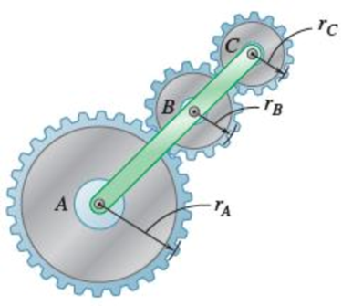
Fig. P15.72
Expert Solution & Answer
Want to see the full answer?
Check out a sample textbook solution
Students have asked these similar questions
The gears shown in the figure have a diametral pitch of 2 teeth per inch and a 20° pressure angle.
The pinion rotates at 1800 rev/min clockwise and transmits 200 hp through the idler pair to gear
5 on shaft c. What forces do gears 3 and 4 transmit to the idler shaft?
TS
I
y
18T
32T
This
a
12
x
18T
C
48T
5
Question 1. Draw 3 teeth for the following pinion and gear respectively. The teeth
should be drawn near the pressure line so that the teeth from the pinion should
mesh those of the gear. Drawing scale (1:1). Either a precise hand drawing or
CAD drawing is acceptable. Draw all the trajectories of the involute lines and the
circles.
Specification: 18tooth pinion and 30tooth gear. Diameter pitch=P=6 teeth /inch.
Pressure angle:20°, 1/P for addendum (a) and 1.25/P for dedendum (b). For fillet,
c=b-a.
5. The figure shows a gear train. There is no friction at the bearings except for the gear tooth forces.
The material of the milled gears is steel having a Brinell hardness of 170. The input shaft speed (n2)
is 800 rpm. The face width and the contact angle for all gears are 1 in and 20° respectively. In this
gear set, the endurance limit (Se) is 15 kpsi and nd (design factor) is 2.
(a) Find the revolution speed of gear 5.
(b) Determine whether each gear satisfies the design factor of 2.0 for bending fatigue.
(c) Determine whether each gear satisfies the design factor of 2.0 for surface fatigue (contact stress).
(d) According to the computation results of the questions (b) and (c), explain the possible failure
mechanisms for each gear.
N4=28
800rpm
N₁=43
N5=34
N₂=14
P(diameteral pitch)=8 for all gears
Coupled to 2.5hp motor
Chapter 15 Solutions
VECTOR MECHANICS FOR ENGINEERS W/CON >B
Ch. 15.1 - A rectangular plate swings from arms of equal...Ch. 15.1 - Knowing that wheel A rotates with a constant...Ch. 15.1 - The brake drum is attached to a larger flywheel...Ch. 15.1 - The motion of an oscillating flywheel is defined...Ch. 15.1 - The motion of an oscillating flywheel is defined...Ch. 15.1 - As steam is slowly injected into a turbine, the...Ch. 15.1 - A small grinding wheel is attached to the shaft of...Ch. 15.1 - A connecting rod is supported by a knife-edge at...Ch. 15.1 - Prob. 15.7PCh. 15.1 - The angular acceleration of an oscillating disk is...
Ch. 15.1 - The angular acceleration of a shaft is defined by...Ch. 15.1 - The assembly shown consists of two rods and a...Ch. 15.1 - In Prob. 15.10, determine the velocity and...Ch. 15.1 - Prob. 15.12PCh. 15.1 - The rectangular block shown rotates about the...Ch. 15.1 - A circular plate of 120-mm radius is supported by...Ch. 15.1 - Prob. 15.15PCh. 15.1 - Prob. 15.16PCh. 15.1 - The earth makes one complete revolution on its...Ch. 15.1 - The sprocket wheel and chain shown are initially...Ch. 15.1 - Prob. 15.19PCh. 15.1 - Prob. 15.20PCh. 15.1 - The rated speed of drum B of the belt sander shown...Ch. 15.1 - The two pulleys shown may be operated with the V...Ch. 15.1 - A cyclist uses a stationary trainer during the...Ch. 15.1 - A gear reduction system consists of three gears A,...Ch. 15.1 - A belt is pulled to the right between cylinders A...Ch. 15.1 - Prob. 15.26PCh. 15.1 - Prob. 15.27PCh. 15.1 - A plastic film moves over two drums. During a 4-s...Ch. 15.1 - Cylinder A is moving downward with a velocity of 3...Ch. 15.1 - The system shown is held at rest by the...Ch. 15.1 - A load is to be raised 20 ft by the hoisting...Ch. 15.1 - A simple friction drive consists of two disks A...Ch. 15.1 - Prob. 15.33PCh. 15.1 - Two friction disks A and B are to be brought into...Ch. 15.1 - Two friction disks A and B are brought into...Ch. 15.1 - Steel tape is being wound onto a spool that...Ch. 15.1 - In a continuous printing process, paper is drawn...Ch. 15.2 - The ball rolls without slipping on the fixed...Ch. 15.2 - Three uniform rodsABC, DCE, and FGHare connected...Ch. 15.2 - Prob. 15.38PCh. 15.2 - An overhead door is guided by wheels at A and B...Ch. 15.2 - A painter is halfway up a 10-m ladder when the...Ch. 15.2 - Rod AB can slide freely along the floor and the...Ch. 15.2 - Rod AB can slide freely along the floor and the...Ch. 15.2 - Rod AB moves over a small wheel at C while end A...Ch. 15.2 - The disk shown moves in the xy plane. Knowing that...Ch. 15.2 - The disk shown moves in the xy plane. Knowing that...Ch. 15.2 - Prob. 15.46PCh. 15.2 - Velocity sensors are placed on a satellite that is...Ch. 15.2 - In the planetary gear system shown, the radius of...Ch. 15.2 - Prob. 15.49PCh. 15.2 - The outer gear C rotates with an angular velocity...Ch. 15.2 - Prob. 15.51PCh. 15.2 - A simplified gear system for a mechanical watch is...Ch. 15.2 - 15.53 and 15.54Arm ACB rotates about point C with...Ch. 15.2 - 15.53 and 15.54Arm ACB rotates about point C with...Ch. 15.2 - Knowing that at the instant shown the angular...Ch. 15.2 - Knowing that at the instant shown the velocity of...Ch. 15.2 - Knowing that the disk has a constant angular...Ch. 15.2 - The disk has a constant angular velocity of 20...Ch. 15.2 - The test rig shown was developed to perform...Ch. 15.2 - Prob. 15.60PCh. 15.2 - In the engine system shown, l = 160 mm and b = 60...Ch. 15.2 - In the engine system shown, l = 160 mm and b = 60...Ch. 15.2 - Knowing that the angular velocity of rod DE is a...Ch. 15.2 - In the position shown, bar AB has an angular...Ch. 15.2 - Prob. 15.65PCh. 15.2 - Prob. 15.66PCh. 15.2 - Prob. 15.67PCh. 15.2 - Prob. 15.68PCh. 15.2 - For the oil pump rig shown, link AB causes the...Ch. 15.2 - Both 6-in.-radius wheels roll without slipping on...Ch. 15.2 - The 80-mm-radius wheel shown rolls to the left...Ch. 15.2 - For the gearing shown, derive an expression for...Ch. 15.3 - The disk rolls without sliding on the fixed...Ch. 15.3 - Prob. 15.6CQCh. 15.3 - A juggling club is thrown vertically into the air....Ch. 15.3 - At the instant shown during deceleration, the...Ch. 15.3 - A helicopter moves horizontally in the x direction...Ch. 15.3 - Prob. 15.76PCh. 15.3 - Prob. 15.77PCh. 15.3 - Prob. 15.78PCh. 15.3 - In order to uncoil electrical wire from a spool...Ch. 15.3 - The arm ABC rotates with an angular velocity of 4...Ch. 15.3 - The double gear rolls on the stationary left rack...Ch. 15.3 - Prob. 15.82PCh. 15.3 - Rod ABD is guided by wheels at A and B that roll...Ch. 15.3 - Knowing that at the instant shown the angular...Ch. 15.3 - Knowing that at the instant shown the velocity of...Ch. 15.3 - A motor at O drives the windshield wiper mechanism...Ch. 15.3 - Prob. 15.88PCh. 15.3 - Small wheels have been attached to the ends of bar...Ch. 15.3 - Prob. 15.90PCh. 15.3 - The disk is released from rest and rolls down the...Ch. 15.3 - Prob. 15.92PCh. 15.3 - Two identical rods ABF and DBE are connected by a...Ch. 15.3 - Arm ABD is connected by pins to a collar at B and...Ch. 15.3 - Two rods ABD and DE are connected to three collars...Ch. 15.3 - Two 500-mm rods are pin-connected at D as shown....Ch. 15.3 - At the instant shown, the velocity of collar A is...Ch. 15.3 - Prob. 15.98PCh. 15.3 - Describe the space centrode and the body centrode...Ch. 15.3 - Describe the space centrode and the body centrode...Ch. 15.3 - Prob. 15.101PCh. 15.3 - Using the method of Sec. 15.3, solve Prob. 15.64....Ch. 15.3 - Using the method of Sec. 15.3, solve Prob. 15.65....Ch. 15.3 - Using the method of Sec. 15.3, solve Prob. 15.38....Ch. 15.4 - A rear-wheel-drive car starts from rest and...Ch. 15.4 - Fig. P15.105 and P15.106 15.105A 5-m steel beam is...Ch. 15.4 - For a 5-m steel beam AE, the acceleration of point...Ch. 15.4 - A 900-mm rod rests on a horizontal table. A force...Ch. 15.4 - In Prob. 15.107, determine the point of the rod...Ch. 15.4 - Knowing that point A is moving to the right at a...Ch. 15.4 - Knowing that at the instant shown crank BC has a...Ch. 15.4 - An automobile travels to the left at a constant...Ch. 15.4 - The 18-in.-radius flywheel is rigidly attached to...Ch. 15.4 - 15.113 and 15.114A 3-in.-radius drum is rigidly...Ch. 15.4 - 15.113 and 15.114A 3-in.-radius drum is rigidly...Ch. 15.4 - A heavy crate is being moved a short distance...Ch. 15.4 - Prob. 15.116PCh. 15.4 - The 100-mm-radius drum rolls without slipping on a...Ch. 15.4 - In the planetary gear system shown, the radius of...Ch. 15.4 - The 200-mm-radius disk rolls without sliding on...Ch. 15.4 - Knowing that crank AB rotates about point A with a...Ch. 15.4 - Knowing that crank AB rotates about point A with a...Ch. 15.4 - In the two-cylinder air compressor shown, the...Ch. 15.4 - The right leg of an athlete on a rowing machine...Ch. 15.4 - Arm AB has a constant angular velocity of 16 rad/s...Ch. 15.4 - Arm AB has a constant angular velocity of 16 rad/s...Ch. 15.4 - A straight rack rests on a gear of radius r = 3...Ch. 15.4 - The elliptical exercise machine has fixed axes of...Ch. 15.4 - The elliptical exercise machine has fixed axes of...Ch. 15.4 - Knowing that the angular velocity of rod DE is a...Ch. 15.4 - Knowing that at the instant shown bar DE has an...Ch. 15.4 - 15.131 and 15.132Knowing that at the instant shown...Ch. 15.4 - 15.131 and 15.132Knowing that at the instant shown...Ch. 15.4 - 15.133 and 15.134Knowing that at the instant shown...Ch. 15.4 - 15.133 and 15.134Knowing that at the instant shown...Ch. 15.4 - Prob. 15.135PCh. 15.4 - For the oil pump rig shown, link AB causes the...Ch. 15.4 - Denoting by rA the position vector of a point A of...Ch. 15.4 - Prob. 15.138PCh. 15.4 - Prob. 15.139PCh. 15.4 - Prob. 15.140PCh. 15.4 - Prob. 15.141PCh. 15.4 - Prob. 15.142PCh. 15.4 - Prob. 15.143PCh. 15.4 - Crank AB rotates with a constant clockwise angular...Ch. 15.4 - Crank AB rotates with a constant clockwise angular...Ch. 15.4 - Solve the engine system from Sample Prob. 15.15...Ch. 15.4 - Prob. 15.147PCh. 15.4 - Prob. 15.148PCh. 15.4 - Prob. 15.149PCh. 15.5 - A person walks radially inward on a platform that...Ch. 15.5 - The motion of pin P is guided by slots cut in rods...Ch. 15.5 - The motion of pin P is guided by slots cut in rods...Ch. 15.5 - 15.152 and 15.153Two rotating rods are connected...Ch. 15.5 - 15.152 and 15.153Two rotating rods are connected...Ch. 15.5 - Pin P is attached to the wheel shown and slides in...Ch. 15.5 - Knowing that at the instant shown the angular...Ch. 15.5 - Prob. 15.156PCh. 15.5 - The motion of pin P is guided by slots cut in rods...Ch. 15.5 - Prob. 15.158PCh. 15.5 - Prob. 15.159PCh. 15.5 - Prob. 15.160PCh. 15.5 - Pin P is attached to the collar shown; the motion...Ch. 15.5 - Prob. 15.162PCh. 15.5 - Prob. 15.163PCh. 15.5 - At the instant shown, the length of the boom AB is...Ch. 15.5 - At the instant shown, the length of the boom AB is...Ch. 15.5 - Prob. 15.166PCh. 15.5 - Prob. 15.167PCh. 15.5 - Prob. 15.168PCh. 15.5 - 15.168 and 15.169A chain is looped around two...Ch. 15.5 - Prob. 15.170PCh. 15.5 - Prob. 15.171PCh. 15.5 - The collar P slides outward at a constant relative...Ch. 15.5 - Pin P slides in a circular slot cut in the plate...Ch. 15.5 - Prob. 15.174PCh. 15.5 - Prob. 15.175PCh. 15.5 - Knowing that at the instant shown the rod attached...Ch. 15.5 - Prob. 15.177PCh. 15.5 - In Prob. 15.177, determine the angular velocity...Ch. 15.5 - At the instant shown, bar BC has an angular...Ch. 15.5 - Prob. 15.180PCh. 15.5 - Rod AB passes through a collar that is welded to...Ch. 15.5 - Prob. 15.182PCh. 15.5 - Prob. 15.183PCh. 15.6 - The bowling ball shown rolls without slipping on...Ch. 15.6 - Prob. 15.185PCh. 15.6 - Prob. 15.186PCh. 15.6 - Prob. 15.187PCh. 15.6 - The rotor of an electric motor rotates at the...Ch. 15.6 - Prob. 15.189PCh. 15.6 - Prob. 15.190PCh. 15.6 - In the system shown, disk A is free to rotate...Ch. 15.6 - Prob. 15.192PCh. 15.6 - Prob. 15.193PCh. 15.6 - A radar system is used to track a new experimental...Ch. 15.6 - A 3-in.-radius disk spins at the constant rate 2 =...Ch. 15.6 - Prob. 15.196PCh. 15.6 - The cone shown rolls on the zx plane with its apex...Ch. 15.6 - At the instant shown, the robotic arm ABC is being...Ch. 15.6 - Prob. 15.199PCh. 15.6 - Prob. 15.200PCh. 15.6 - Several rods are brazed together to form the...Ch. 15.6 - In Prob. 15.201, the speed of point B is known to...Ch. 15.6 - Prob. 15.203PCh. 15.6 - Prob. 15.204PCh. 15.6 - Rod BC and BD are each 840 mm long and are...Ch. 15.6 - Rod AB is connected by ball-and-socket joints to...Ch. 15.6 - Prob. 15.207PCh. 15.6 - Prob. 15.208PCh. 15.6 - Prob. 15.209PCh. 15.6 - Prob. 15.210PCh. 15.6 - Prob. 15.211PCh. 15.6 - Prob. 15.212PCh. 15.6 - Prob. 15.213PCh. 15.6 - Prob. 15.214PCh. 15.6 - In Prob. 15.205, determine the acceleration of...Ch. 15.6 - In Prob. 15.206, determine the acceleration of...Ch. 15.6 - In Prob. 15.207, determine the acceleration of...Ch. 15.6 - Prob. 15.218PCh. 15.6 - Prob. 15.219PCh. 15.7 - A flight simulator is used to train pilots on how...Ch. 15.7 - A flight simulator is used to train pilots on how...Ch. 15.7 - Prob. 15.222PCh. 15.7 - Prob. 15.223PCh. 15.7 - Prob. 15.224PCh. 15.7 - The bent rod shown rotates at the constant rate of...Ch. 15.7 - The bent pipe shown rotates at the constant rate 1...Ch. 15.7 - The circular plate shown rotates about its...Ch. 15.7 - Prob. 15.228PCh. 15.7 - Prob. 15.229PCh. 15.7 - Prob. 15.230PCh. 15.7 - Prob. 15.231PCh. 15.7 - Using the method of Sec. 15.7A, solve Prob....Ch. 15.7 - Prob. 15.233PCh. 15.7 - Prob. 15.234PCh. 15.7 - Prob. 15.235PCh. 15.7 - The arm AB of length 16 ft is used to provide an...Ch. 15.7 - The remote manipulator system (RMS) shown is used...Ch. 15.7 - A disk with a radius of 120 mm rotates at the...Ch. 15.7 - Prob. 15.239PCh. 15.7 - Prob. 15.240PCh. 15.7 - Prob. 15.241PCh. 15.7 - The cylinder shown rotates at the constant rate 2...Ch. 15.7 - Prob. 15.243PCh. 15.7 - Prob. 15.244PCh. 15.7 - Prob. 15.245PCh. 15.7 - Prob. 15.246PCh. 15.7 - Prob. 15.247PCh. 15 - A wheel moves in the xy plane in such a way that...Ch. 15 - Two blocks and a pulley are connected by...Ch. 15 - A baseball pitching machine is designed to deliver...Ch. 15 - The flywheel OD on the elliptical machine analyzed...Ch. 15 - The roller at point A on the elliptical machine...Ch. 15 - Knowing that at the instant shown rod AB has zero...Ch. 15 - Rod AB is attached to a collar at A and is fitted...Ch. 15 - Prob. 15.255RPCh. 15 - A disk of 0.15-m radius rotates at the constant...Ch. 15 - Prob. 15.257RPCh. 15 - Prob. 15.258RPCh. 15 - In the position shown, the thin rod moves at a...
Knowledge Booster


Learn more about
Need a deep-dive on the concept behind this application? Look no further. Learn more about this topic, mechanical-engineering and related others by exploring similar questions and additional content below.Similar questions
- 1. The rotating steel shaft is simply supported by bearings at points of B and C, and is driven by a spur gear at D, which has a 6-in pitch diameter. The force F from the drive gear acts at a pressure angle of 20°. The shaft transmits a torque to point A of TA =3000 lbĘ in. The shaft is machined from steel with Sy=60kpsi and Sut=80 kpsi. (1) Draw a shear force diagram and a bending moment diagram by F. According to your analysis, where is the point of interest to evaluate the safety factor among A, B, C, and D? Describe the reason. (Hint: To find F, the torque Tд is generated by the tangential force of F (i.e. Ftangential-Fcos20°) When n=2.5, K=1.8, and K₁ =1.3, determine the diameter of the shaft based on (2) static analysis using DE theory (note that fatigue stress concentration factors need to be used for this question because the loading condition is fatigue) and (3) a fatigue analysis using modified Goodman. Note) A standard diameter is not required for the questions. 10 in Darrow_forward3 N2=28 P(diametral pitch)=8 for all gears Coupled to 25 hp motor N3=34 Full depth spur gears with pressure angle=20° N₂=2000 rpm (1) Compute the circular pitch, the center-to-center distance, and base circle radii. (2) Draw the free body diagram of gear 3 and show all the forces and the torque. (3) In mounting gears, the center-to-center distance was reduced by 0.1 inch. Calculate the new values of center-to-center distance, pressure angle, base circle radii, and pitch circle diameters. (4)What is the new tangential and radial forces for gear 3? (5) Under the new center to center distance, is the contact ratio (mc) increasing or decreasing?arrow_forward2. A flat belt drive consists of two 4-ft diameter cast-iron pulleys spaced 16 ft apart. A power of 60 hp is transmitted by a pulley whose speed is 380 rev/min. Use a service factor (Ks) pf 1.1 and a design factor 1.0. The width of the polyamide A-3 belt is 6 in. Use CD=1. Answer the following questions. (1) What is the total length of the belt according to the given geometry? (2) Find the centrifugal force (Fc) applied to the belt. (3) What is the transmitted torque through the pulley system given 60hp? (4) Using the allowable tension, find the force (F₁) on the tight side. What is the tension at the loose side (F2) and the initial tension (F.)? (5) Using the forces, estimate the developed friction coefficient (f) (6) Based on the forces and the given rotational speed, rate the pulley set. In other words, what is the horse power that can be transmitted by the pulley system? (7) To reduce the applied tension on the tight side, the friction coefficient is increased to 0.75. Find out the…arrow_forward
- The tooth numbers for the gear train illustrated are N₂ = 24, N3 = 18, №4 = 30, №6 = 36, and N₁ = 54. Gear 7 is fixed. If shaft b is turned through 5 revolutions, how many turns will shaft a make? a 5 [6] barrow_forwardCE-112 please solve this problem step by step and give me the correct answerarrow_forwardCE-112 please solve this problem step by step and give me the correct answerarrow_forward
- CE-112 solve this problem step by step and give me the correct answer pleasearrow_forwardPlease do not use any AI tools to solve this question. I need a fully manual, step-by-step solution with clear explanations, as if it were done by a human tutor. No AI-generated responses, please.arrow_forwardPlease do not use any AI tools to solve this question. I need a fully manual, step-by-step solution with clear explanations, as if it were done by a human tutor. No AI-generated responses, please.arrow_forward
arrow_back_ios
SEE MORE QUESTIONS
arrow_forward_ios
Recommended textbooks for you
 Principles of Heat Transfer (Activate Learning wi...Mechanical EngineeringISBN:9781305387102Author:Kreith, Frank; Manglik, Raj M.Publisher:Cengage Learning
 International Edition---engineering Mechanics: St...Mechanical EngineeringISBN:9781305501607Author:Andrew Pytel And Jaan KiusalaasPublisher:CENGAGE L
 Precision Machining Technology (MindTap Course Li...Mechanical EngineeringISBN:9781285444543Author:Peter J. Hoffman, Eric S. Hopewell, Brian JanesPublisher:Cengage Learning
 Automotive Technology: A Systems Approach (MindTa...Mechanical EngineeringISBN:9781133612315Author:Jack Erjavec, Rob ThompsonPublisher:Cengage Learning
 Welding: Principles and Applications (MindTap Cou...Mechanical EngineeringISBN:9781305494695Author:Larry JeffusPublisher:Cengage Learning
 Automotive TechnologyMechanical EngineeringISBN:9781337794213Author:ERJAVEC, Jack.Publisher:Cengage,
Principles of Heat Transfer (Activate Learning wi...
Mechanical Engineering
ISBN:9781305387102
Author:Kreith, Frank; Manglik, Raj M.
Publisher:Cengage Learning
International Edition---engineering Mechanics: St...
Mechanical Engineering
ISBN:9781305501607
Author:Andrew Pytel And Jaan Kiusalaas
Publisher:CENGAGE L
Precision Machining Technology (MindTap Course Li...
Mechanical Engineering
ISBN:9781285444543
Author:Peter J. Hoffman, Eric S. Hopewell, Brian Janes
Publisher:Cengage Learning
Automotive Technology: A Systems Approach (MindTa...
Mechanical Engineering
ISBN:9781133612315
Author:Jack Erjavec, Rob Thompson
Publisher:Cengage Learning
Welding: Principles and Applications (MindTap Cou...
Mechanical Engineering
ISBN:9781305494695
Author:Larry Jeffus
Publisher:Cengage Learning
Automotive Technology
Mechanical Engineering
ISBN:9781337794213
Author:ERJAVEC, Jack.
Publisher:Cengage,
Dynamics - Lesson 1: Introduction and Constant Acceleration Equations; Author: Jeff Hanson;https://www.youtube.com/watch?v=7aMiZ3b0Ieg;License: Standard YouTube License, CC-BY