Introductory Circuit Analysis (13th Edition)
13th Edition
ISBN: 9780133923605
Author: Robert L. Boylestad
Publisher: PEARSON
expand_more
expand_more
format_list_bulleted
Textbook Question
Chapter 15, Problem 30P
For the circuit in Fig. 15.106:
a. Plot
b. Plot
c. Plot
d. Plot

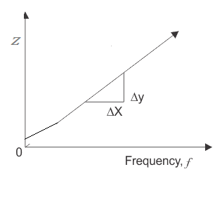
Fig. 15.106
Expert Solution & Answer
Want to see the full answer?
Check out a sample textbook solution
Students have asked these similar questions
A left-sided signal x(t)=-ebt u(-t):
A right-sided signal x(t)=e¯at u(t)
Find Laplace transform of x(t)=u(t)
Find Laplace transform of x(t) = −e¯btu(−t) + e¯atu(t)
Find Laplace transform of x(t) = u(t)
Expert only, don't use artificial intelligence ,or screenshot of an AI solving steps
Chapter 15 Solutions
Introductory Circuit Analysis (13th Edition)
Ch. 15 - For the resistive element in Fig. 15.81: Write the...Ch. 15 - For the resistive element in Fig. 15.82: Write the...Ch. 15 - For the inductive element of Fig. 15.83: a. Write...Ch. 15 - For the inductive element of Fig. 15.84: Calculate...Ch. 15 - For the inductive element of Fig. 15.85: Write the...Ch. 15 - For the capacitive element of Fig. 15.86: Write...Ch. 15 - For the capacitive element of Fig. 15.87:...Ch. 15 - For the capacitive element of Fig. 15.88: Write...Ch. 15 - Sketch the impedance diagram of a 120 k resistor.Ch. 15 - Sketch the impedance diagram of a 5 mH coil...
Ch. 15 - Sketch the impedance diagram of a 0.02 F capacitor...Ch. 15 - Calculate the total impedance of the circuits in...Ch. 15 - Calculate the total impedance of the circuits in...Ch. 15 - Find the type and impedance in ohms of the series...Ch. 15 - For the circuit in Fig. 15.92 Find the total...Ch. 15 - Repeat problem 15 for the circuit in Fig. 15.93,...Ch. 15 - For the circuit in Fig. 15.94: Find the total...Ch. 15 - Repeat Problem 17 for the circuit in Fig. 15.95...Ch. 15 - For the circuit of Fig. 15.96: Find the total...Ch. 15 - For the circuit of Fig. 15.97: Find the current...Ch. 15 - Prob. 21PCh. 15 - Using the oscilloscope reading in Fig. 15.99,...Ch. 15 - Using the DMM current reading and the oscilloscope...Ch. 15 - Using the oscilloscope reading in Fig. 15.101:...Ch. 15 - An electrical load has a power factor of 0.8...Ch. 15 - Find the series element or elements that must be...Ch. 15 - Calculate the voltages V1andV2 for the circuits in...Ch. 15 - Calculate the voltages V1andV2 for the circuits in...Ch. 15 - For the circuit in Fig. 15.105: Determine...Ch. 15 - For the circuit in Fig. 15.106: a. Plot ZT and T...Ch. 15 - Prob. 31PCh. 15 - For the series R-L-C circuit in Fig. 15.108: Plot...Ch. 15 - For the series R-C circuit in Fig. 15.109:...Ch. 15 - For the circuit in Fig. 15.110, determine the...Ch. 15 - For the oscilloscope traces in Fig. 15.111:...Ch. 15 - For the network in Fig. 15.92 (usef=1kHz):...Ch. 15 - For the network in Fig. 15.93: Plot the impedance...Ch. 15 - For the network in Fig. 15.105: Find the rms...
Knowledge Booster
Learn more about
Need a deep-dive on the concept behind this application? Look no further. Learn more about this topic, electrical-engineering and related others by exploring similar questions and additional content below.Similar questions
- find inverse LT for the following functions 1- [0.2s+1.4] s2+1.96. 2. L-1 5s+1 Ls2-25. 4s+32 3. L- L(s2-16).arrow_forwardQ Figurel shows the creation of the Frequency Reuse Pattern Using the Cluster Size K (A) illustrates how i and j can be used to locate a co-channel cell. Juster Cluster CB Cluster 2 X=7(i=2,j=1)arrow_forwardDon't use ai to answer I will report you answerarrow_forward
- Q2. For the transformer shown in Fig. 1. A. Plot the winding connection for the transformer and justify your answer. (4M) B. If the transformer is adopted in 12 pulse diode rectifier, where two-series connected bridge rectifiers are used to supply a highly inductive load with 100 A. (i) Select a suitable turns ratio for the transformer (ii) Plot the line current of each winding ( secondary + primary) showing the current magnitude at each interval (iii) Use Fourier Page 1 of 3 analysis to obtain the Fourier series of all line currents then calculate the THD of the input current. (8=0° (16M) (Y) = 30° Fig. 1 P. I v Iarrow_forwardQ2. For the transformer shown in Fig.1, A. Find the phase shift between the primary and star-connected secondary. B. If the transformer is adopted in a 12-pulse diode rectifier, where a two-series connected bridge rectifier is connected in series and supplies a highly inductive load (i) Select a suitable turns ratio for the transformer (ii) Plot the line current of each winding (secondary + primary). (iii)Using Fourier analysis to obtain the Fourier series of all line currents, then calculate the THD of the input current. (iv) Draw the output voltage of the first and second rectifiers and give the relation of the total output voltage. N2 B C Fig. 1 N3 aarrow_forwardQ2.A. It is planned to use the transformer shown in Fig. 1, a 12-pulse rectifier. Each secondary is connected to three phase controlled bridge rectifier. The two rectifiers are connected in series to supply a highly inductive load. 1. Based on the phasor relationship between different windings. If suitable turns ratio is selected, is it possible to use this transformer to produce 12 pulse output voltage? Show the reason behind your answer. 2. Assuming this arrangement is possible to be used in 12-pulse rectifier, draw the output voltage of the 1st and 2nd rectifier and give the relation of the total output voltage. 3. Use the Fourier analysis to show the harmonics in all line currents of the transformer. A B in C Fig. 1 b la a 2 b.arrow_forward
arrow_back_ios
SEE MORE QUESTIONS
arrow_forward_ios
Recommended textbooks for you

02 - Sinusoidal AC Voltage Sources in Circuits, Part 1; Author: Math and Science;https://www.youtube.com/watch?v=8zMiIHVMfaw;License: Standard Youtube License