
Electronics Fundamentals: Circuits, Devices & Applications
8th Edition
ISBN: 9780135072950
Author: Thomas L. Floyd, David Buchla
Publisher: Prentice Hall
expand_more
expand_more
format_list_bulleted
Concept explainers
Videos
Textbook Question
Chapter 15, Problem 28P
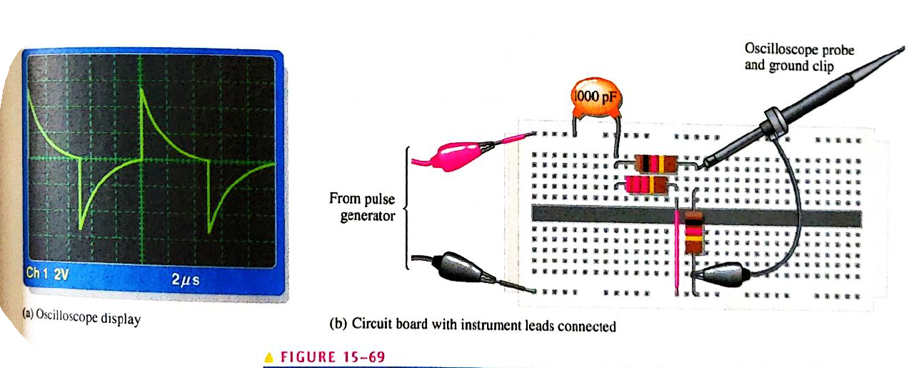
Draw the schematic for the circuit in Figure 15-69 and determine if the oscilloscope presentation is correct.
Expert Solution & Answer
Want to see the full answer?
Check out a sample textbook solution
Students have asked these similar questions
NO AI PLEASE
NO AI PLEASE
Add a second start button to the basic circuit so Start Button 1 or Start Button 2 can be used to start a motor. Include a second stop button that is connected so that Stop Button 1 or Start Button 2 can be used to stop the motor.
Chapter 15 Solutions
Electronics Fundamentals: Circuits, Devices & Applications
Ch. 15 - Transient time for an RC circuit is the same as...Ch. 15 - Prob. 2TFQCh. 15 - If the source voltage is increased in a pulsed RC...Ch. 15 - Prob. 4TFQCh. 15 - Prob. 5TFQCh. 15 - Prob. 6TFQCh. 15 - Prob. 7TFQCh. 15 - Prob. 8TFQCh. 15 - Prob. 9TFQCh. 15 - Prob. 10TFQ
Ch. 15 - Prob. 1STCh. 15 - Prob. 2STCh. 15 - Prob. 3STCh. 15 - Prob. 4STCh. 15 - In an RC differentiator, the output pulse closely...Ch. 15 - Prob. 6STCh. 15 - Prob. 7STCh. 15 - Prob. 8STCh. 15 - Prob. 9STCh. 15 - Prob. 10STCh. 15 - Prob. 1PCh. 15 - Determine how long it takes the capacitor in an...Ch. 15 - Prob. 3PCh. 15 - Prob. 4PCh. 15 - Prob. 5PCh. 15 - Prob. 6PCh. 15 - Show the approximate shape of an integrator output...Ch. 15 - Prob. 8PCh. 15 - Prob. 9PCh. 15 - Prob. 10PCh. 15 - Prob. 11PCh. 15 - Prob. 12PCh. 15 - Prob. 13PCh. 15 - Draw the differentiator output in Figure 15-59....Ch. 15 - Prob. 15PCh. 15 - Prob. 16PCh. 15 - Prob. 17PCh. 15 - Prob. 18PCh. 15 - Prob. 19PCh. 15 - Prob. 20PCh. 15 - Ideally, what is the output of an RC integrator...Ch. 15 - Prob. 22PCh. 15 - Prob. 23PCh. 15 - Prob. 24PCh. 15 - Prob. 25PCh. 15 - Prob. 26PCh. 15 - Prob. 27PCh. 15 - Draw the schematic for the circuit in Figure 15-69...Ch. 15 - Prob. 29PCh. 15 - Prob. 30PCh. 15 - Prob. 31PCh. 15 - Prob. 32P
Knowledge Booster


Learn more about
Need a deep-dive on the concept behind this application? Look no further. Learn more about this topic, electrical-engineering and related others by exploring similar questions and additional content below.Similar questions
- Add a second start button to the basic circuit so Start Button 1 or Start Button 2 can be used to start a motor. Include a second stop button that is connected so that Stop Button 1 or Start Button 2 can be used to stop the motor.arrow_forwardCircuit Logic. Match each statement to the proper circuit. All circuits have been drawn with a light (L) to represent the load, whether it is a motor, bell, or any other kind of load. In addition, each switch is illustrated as a pushbutton whether it is a maintained switch, momentary switch, pushbutton, switch-on target, or any other type of switch. from electrical motor controls for integrated systems workbook 2014 chapter 5arrow_forwardAssume ideal op-amp. If V_DC= 2.9, find I_L in mAarrow_forward
- R is 12 kΩ . Find the Thevenin equivalent resistance.arrow_forwardAssuming an ideal op-amp, design an inverting amplifier with a gain of 25 dB having the largest possible input resistance under the constraint of having to use resistors no larger than 90 kΩ. What's the input resist?arrow_forwardI need help with this problem and an explanation of the solution for the image described below. (Introduction to Signals and Systems)arrow_forward
- I hope the solution is on paper and not artificial intelligence. The subject is control systemarrow_forwardI hope the solution is on paper and not artificial intelligence.arrow_forwardVs R1 R2 ww ww 21x R3 Define the Thevenin equivalent of the above circuit where R1= 10 52, R2= 30 S2, R3 = 30 12, Vs = 70 V. VThevenin Number V RThevenin = Number Ωarrow_forward
arrow_back_ios
SEE MORE QUESTIONS
arrow_forward_ios
Recommended textbooks for you
 Delmar's Standard Textbook Of ElectricityElectrical EngineeringISBN:9781337900348Author:Stephen L. HermanPublisher:Cengage Learning
Delmar's Standard Textbook Of Electricity
Electrical Engineering
ISBN:9781337900348
Author:Stephen L. Herman
Publisher:Cengage Learning
Current Divider Rule; Author: Neso Academy;https://www.youtube.com/watch?v=hRU1mKWUehY;License: Standard YouTube License, CC-BY