
Concept explainers
Videos
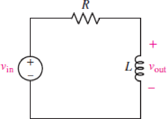
For the RL circuit in Fig. 15.52, (a) determine the transer function defined as H(jω) = vout/vin; (b) for the case of R = 200 Ω and L = 5 mH, construct a plot of the magnitude and phase as a function of frequency; and (c) evaluate the magnitude and phase at a frequency of 10 kHz.
FIGURE 15.52
(a)
Find the transfer function
Answer to Problem 1E
The transfer function
Explanation of Solution
Given data:
Refer to Figure 15.52 in the textbook.
Formula used:
Write the expression to calculate the impedance of the passive elements resistor and inductor.
Here,
Calculation:
The given RL circuit is drawn as Figure 1.
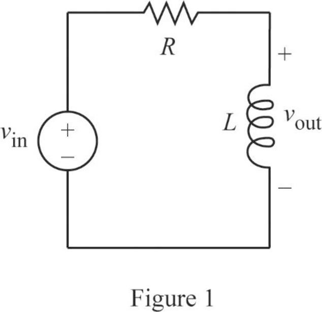
The Figure 1 is redrawn as impedance circuit in Figure 2 using the equations (1) and (2).
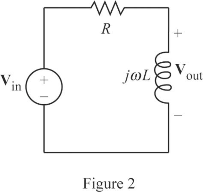
Write the general expression to calculate the transfer function of the circuit in Figure 2.
Here,
Apply Kirchhoff’s voltage law on Figure 2 to find
Rearrange the above equation to find
Substitute
Conclusion:
Thus, the transfer function
(b)
Plot the magnitude and phase as a function of frequency.
Explanation of Solution
Given data:
The value of the resistor
The value of the inductor
Calculation:
From part (a), the transfer function is,
Substitute
Simplify the above equation to find
Re-write the transfer function
From equation (4), the magnitude function of
Write the above equation in decibel (dB).
From equation (4), the phase angle is expressed as follows:
Substitute
Substitute
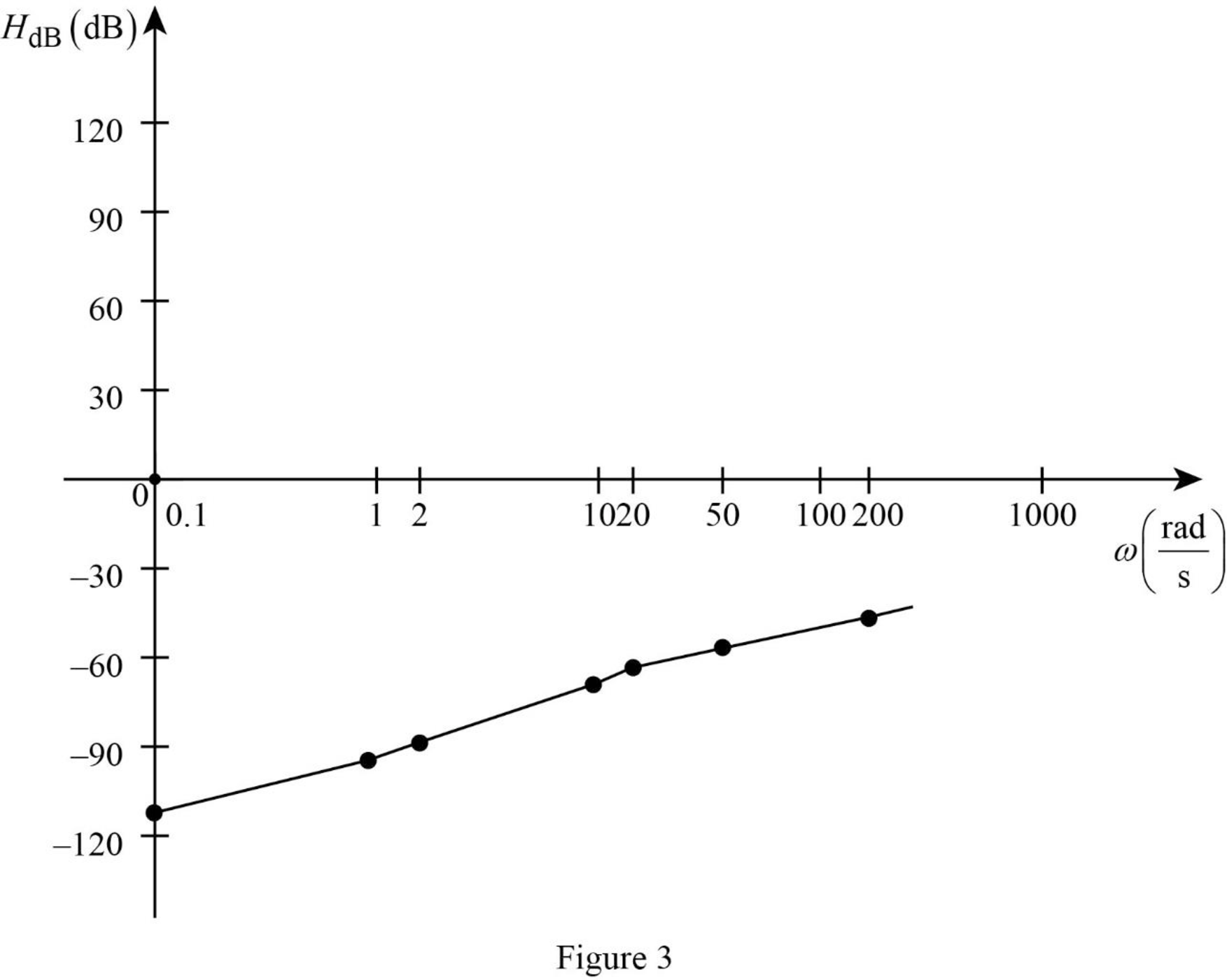
Similarly, by substituting various values for
Table 1
| 0.1 | 1 | 2 | 10 | 20 | 50 | 200 | |
| –112 | –92 | –86 | –72 | –66 | –58 | –46 |
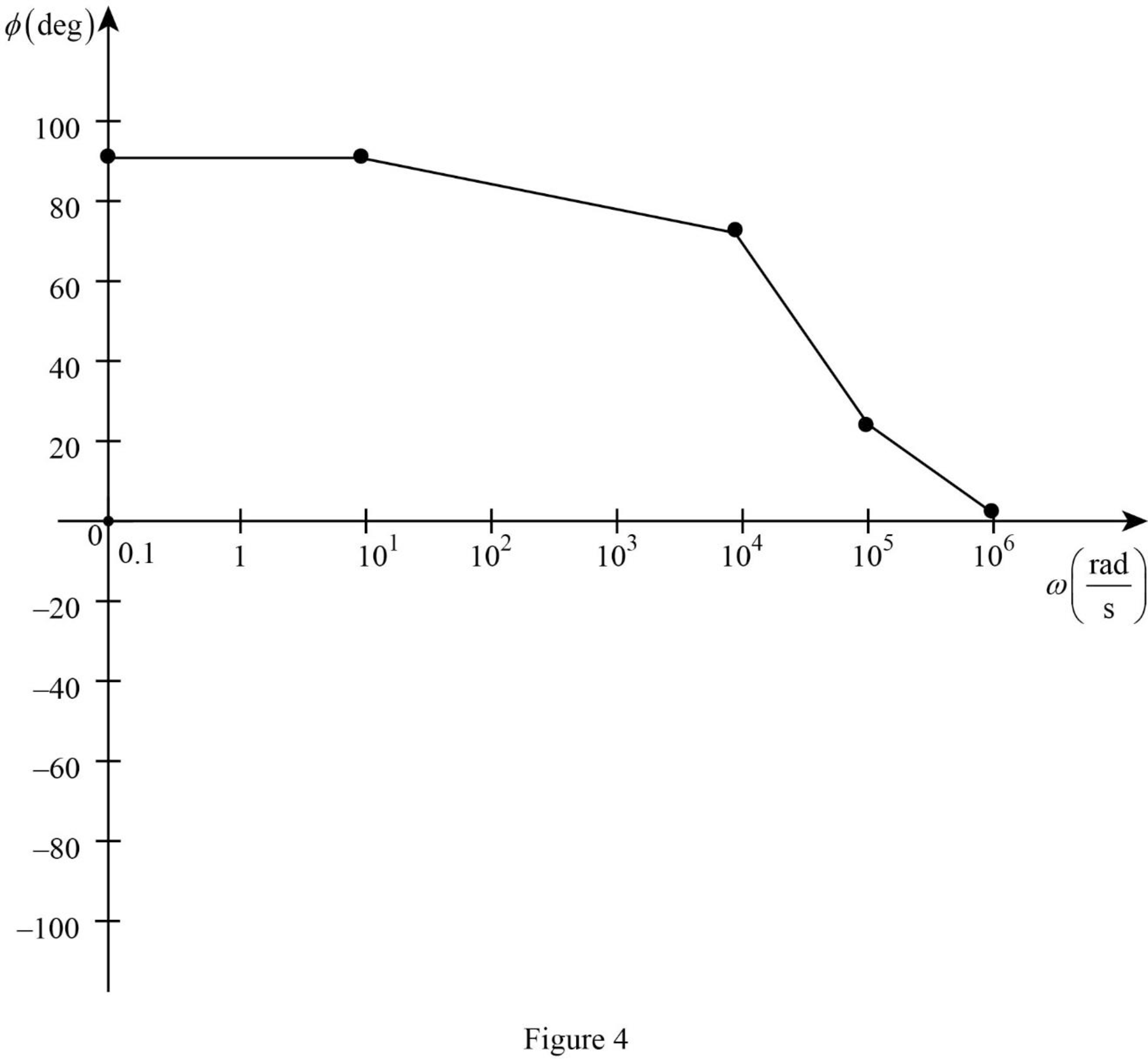
Table 2
| 0.1 | 10 | 104 | 105 | 106 | |
| 90 | 90 | 75.96 | 21.8 | 2.3 |
The Figure 1 is the magnitude plot of the given transfer function obtained using Table 1.
The Figure 2 is the phase plot of the given transfer function obtained using Table 2.
Conclusion:
Thus, the magnitude and phase as a function of frequency is plotted.
(c)
Find the value of the magnitude and phase at a frequency of
Answer to Problem 1E
The value of the magnitude and phase at a frequency of
Explanation of Solution
Given data:
The value of the frequency
Formula used:
Write the expression to calculate the angular frequency.
Here,
Calculation:
From part (a), the transfer function is expressed as,
From equation (7), the magnitude function is expressed as,
Substitute
Substitute
From equation (7), the phase function is expressed as,
Substitute
Substitute
Conclusion:
Thus, the value of the magnitude and phase at a frequency of
Want to see more full solutions like this?
Chapter 15 Solutions
Loose Leaf for Engineering Circuit Analysis Format: Loose-leaf
Additional Engineering Textbook Solutions
Management Information Systems: Managing The Digital Firm (16th Edition)
Starting Out with Java: From Control Structures through Objects (7th Edition) (What's New in Computer Science)
SURVEY OF OPERATING SYSTEMS
Starting Out with Programming Logic and Design (5th Edition) (What's New in Computer Science)
Electric Circuits. (11th Edition)
Concepts Of Programming Languages


- = = For the circuit shown, let V, 15 V, I, 4A, R₁ =5, R₂ 10, R3 10, and R4 5. Determine the output voltage Vo as follows All resistor values are in ohms. 1. Identify the supermesh and write its corresponding Mesh equation. Provide your expression in terms of the shown mesh current i₁, and 12 of the form (R11 · 11+ R12 · 12 = V₁), then enter the corresponding values: R11 Ω R12 V₁= V Ω 2. Use the above equation, and supermesh inner expression to calculate i₂: i₂- Find Vo V₁ = A V R₁ www M R3 ww V R4 V₁ 0 IS R₁ The relative tolerance for this problem is 7 %. 0arrow_forward11.18 In the circuit of Fig. P11.18, what should the value of thecoupling coefficient k be so that Vout/Vin = 0.49?arrow_forward11.26 Determine the complex power supplied by the source inthe circuit of Fig. P11.26.arrow_forward
- 11.23 Determine Vout in the circuit of Fig. P11.23arrow_forwardReversing 1⏀ Motors-all the wires are not used. Use the data sheet b on page 383 to draw the wiring diagram. Note: interchange the red and black leads to reverse the motor rotation. Use only the number of contacts required. Insulate any motor wire not used with a wire nut. Wire the motor to operate in forward and reverse at 115 VACarrow_forwardSee both images to answerarrow_forward
- See both images to answerarrow_forwardAn inner-city electric bus with 7,200kg weight and average speed of 72 km/hour operates using a hybrid power source of lithium-ion battery pack and a bank of super capacitor. equipped with a lithium battery pack and a bank of supercapacitor. The energy content of the supercapacitor bank is twice the regenerative breaking energy of the electric bus at average speed. The electric bus commutes 490 km per charged battery and consumes 400 Wh/km. Design the supercapacitor bank to provide 100V output, based on supercapacitor cells with 3600F capacitance and 2V. Calculate the energy density of the supercapacitor at the cell level, assume cells with 10cm diameter and 15 cm height. 3. Design the battery pack for the electric bus by assuming that the energy of regenerative breaking will not be used for commuting but used to run the vehicle’s accessories. The unit cell of the battery pack is a lithium-ion…arrow_forwardA rod coincident with the z-axis extends from 0 to -L. If the rod carries a uniform charge density of pL (a) calculate the electric field intensity at a point h on the z-axis. (b) Use your answer to show that when h>>L the rod behaves as a point charge of value plL . (c) How much larger than the length of the rod must h be in order that the answer to part b) is a reasonably accurate estimate.arrow_forward
- The separation of two point charges with charges Q1=36pC and ,Q2=9pC respectively, is 3 cm. If a third point charge Q3 is placed on the line joining Q1 and Q2 at a distance d from Q1 find Q3 and d that ensures that the force on all charges is zero.arrow_forward5. The electric field on the positive z-axis due to a uniformly charged disk of radius a that lies in the x-y plane with center at the origin is claimed to be given by - Ps Z 2E 2 a² + z² Where ps is the surface charge density on the disk. Without deriving this formula, evaluate it for its probable correctness. (a) Is its symmetry correct? Explain. (b) If z>> a, it reduces to that of a point charge of value a²ps (c) if z> z is large the formula reduces to that of an infinite plane.arrow_forwardA rod coincident with the z-axis extends from 0 to L. If the rod carries a uniform charge density of pL , calculate the electric field intensity at a point h on the y-axis.arrow_forward
 Introductory Circuit Analysis (13th Edition)Electrical EngineeringISBN:9780133923605Author:Robert L. BoylestadPublisher:PEARSON
 Delmar's Standard Textbook Of ElectricityElectrical EngineeringISBN:9781337900348Author:Stephen L. HermanPublisher:Cengage Learning
 Programmable Logic ControllersElectrical EngineeringISBN:9780073373843Author:Frank D. PetruzellaPublisher:McGraw-Hill Education
 Fundamentals of Electric CircuitsElectrical EngineeringISBN:9780078028229Author:Charles K Alexander, Matthew SadikuPublisher:McGraw-Hill Education
 Electric Circuits. (11th Edition)Electrical EngineeringISBN:9780134746968Author:James W. Nilsson, Susan RiedelPublisher:PEARSON
 Engineering ElectromagneticsElectrical EngineeringISBN:9780078028151Author:Hayt, William H. (william Hart), Jr, BUCK, John A.Publisher:Mcgraw-hill Education,