
(a)
Find the value of
(a)
Answer to Problem 16E
The value of
Explanation of Solution
Given data:
Refer to Figure 15.53 in the textbook.
Formula used:
Write the expression to calculate the impedance of the passive elements resistor, inductor and capacitor in s-domain.
Here,
Calculation:
Given that the output voltage should be taken across the inductor in series RLC circuit.
Generally, the transfer function of the series RLC circuit for which the output is taken across the inductor is,
The modified circuit of given circuit is drawn as Figure 1.
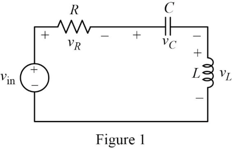
The Figure 1 is redrawn as impedance circuit in s-domain in Figure 2 using the equations (1), (2) and (3).
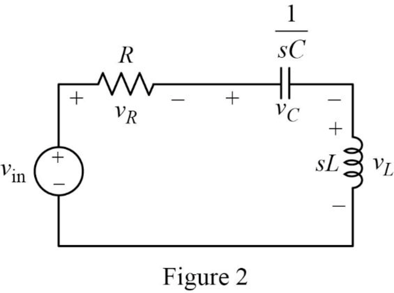
Write the general expression to calculate the transfer function of the circuit in Figure 2.
Here,
Apply Kirchhoff’s voltage law on Figure 2 to find
Rearrange the above equation to find
Substitute
Compare the above equation with the equation (4) to obtain the following values.
Rearrange the equation (6).
Rearrange the above equation to find
Rearrange the equation (7) to find
Substitute
Conclusion:
Thus, the value of
(b)
Find the values of inductor
(b)
Answer to Problem 16E
The value of inductor
Explanation of Solution
Given data:
The value of the resistor
The value of the resonant frequency
Calculation:
Case (i):
From part (a),
Substitute
Rearrange the above equation to find
Rearrange the above equation to find
Rearrange the equation (9).
Rearrange the above equation to find
Substitute
Rearrange the above equation to find
Take square root on both sides of the above equation to find
Substitute
Case (ii):
Substitute
Rearrange the above equation to find
Rearrange the above equation to find
Substitute
Rearrange the above equation to find
Take square root on both sides of the above equation to find
Substitute
Case (iii):
Substitute
Rearrange the above equation to find
Rearrange the above equation to find
Substitute
Rearrange the above equation to find
Take square root on both sides of the above equation to find
Substitute
Conclusion:
Thus, the value of inductor
(c)
Construct the magnitude Bode plots for the three cases
(c)
Explanation of Solution
Calculation:
Simplify the equation (4) to find
Case (i):
Substitute
Case (ii):
Substitute
Case (iii):
Substitute
The equations (15), (16) and (17) are the transfer function of the given series RLC circuit at three different cases
The MATLAB code is given below to sketch the magnitude Bode plots for the three cases using the equations (15), (16) and (17).
MATLAB Code:
clc;
clear all;
close all;
sys1=tf([1 0 0],[1 1000 (25*10^6)]);
sys2=tf([1 0 0],[1 5000 (25*10^6)]);
sys3=tf([1 0 0],[1 10000 (25*10^6)]);
bode(sys1,sys2,sys3)
legend({'sys1','sys2','sys3'},'Location','best')
Output:
The MATLAB output is shown in Figure 3.
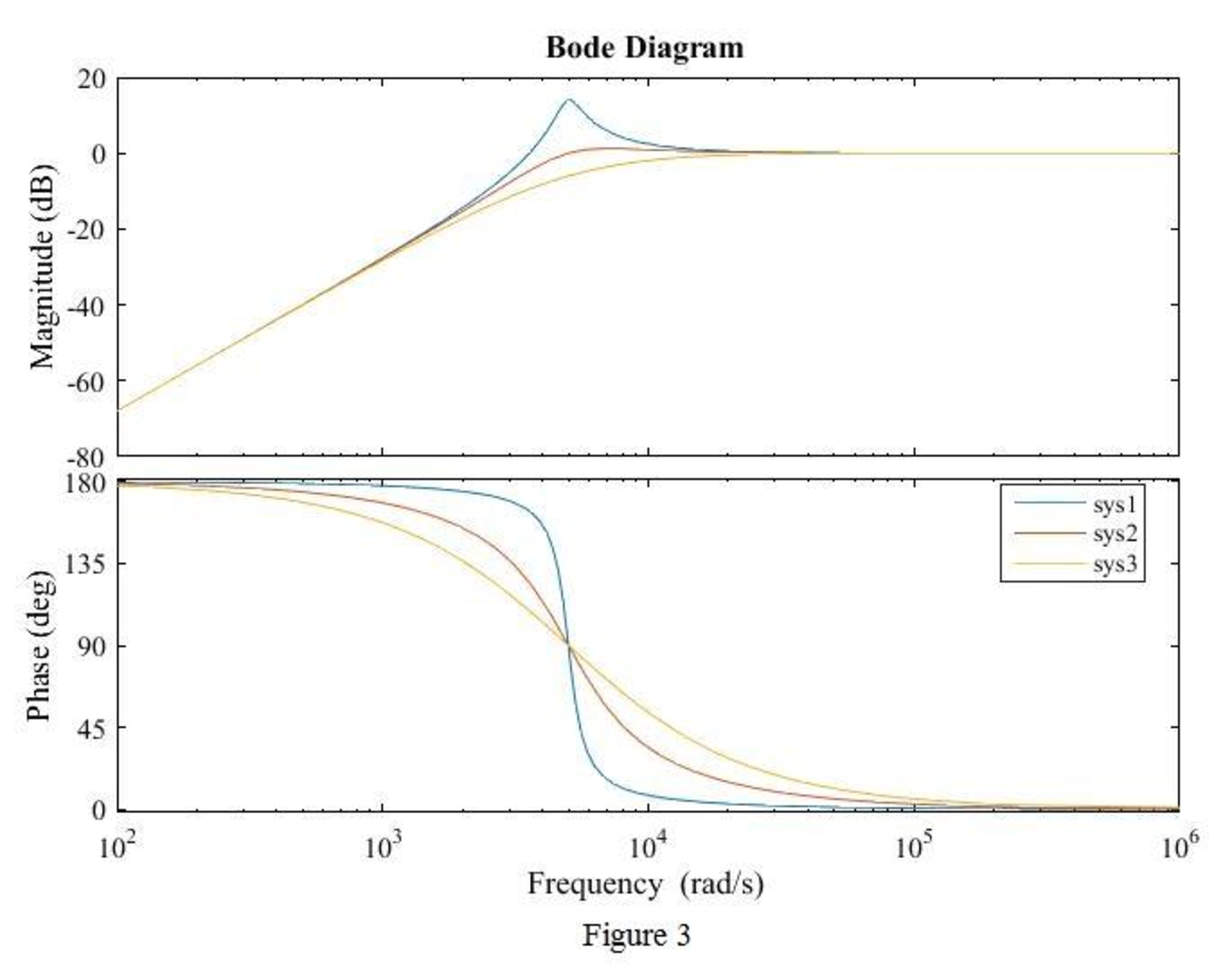
Conclusion:
Thus, the magnitude Bode plot for the three cases
Want to see more full solutions like this?
Chapter 15 Solutions
Loose Leaf for Engineering Circuit Analysis Format: Loose-leaf

- A. Using D flip-flops, design a logic circuit for the finite-state machine described by the state assigned table in Fig. 1. Present Next State State Output x=0 x=1 Y2Y1 Y2Y1 YY Z 00 00 01 0 01 10 11 888 00 10 0 00 10 1 00 10 1 Fig. 1arrow_forwardAthree phase a.c. distributor AB has: A B C The distance from A to B is 500 m. The distance from A to C is 800 m. The impedance of each section is (6+j 8) /km. The voltage at the far end is maintained at 250 volt. Find: sending voltage, sending current, supply power factor and 80A 60 A total voltage drop. 0.8 lag. P.f 0.6 lead. p.farrow_forwardengineering electromagnetics Subjectarrow_forward
- a ADI ADI b Co ADDS D Fig.(2) 2-For resistive load, measure le output voltage by using oscilloscope; then sketch this wave. 3- Measure the average values ::f V₁ and IL: 4- Repeat steps 2 & 3 but for PL load.arrow_forwardDetermine the type of media In a certain medium with µ = o, & = 40 H = 12ely sin(x x 10% - By) a, A/m A plane wave propagating through a medium with ɛ, = 8, μ, = 2 has E = 0.5 3sin(10°t - Bz) a, V/m. Determine In a certain medium - E = 10 cos (2 x 10't ẞx)(a, + a.) V/m If μ == 50μo, & = 2ɛ, and o = 0, In a medium, -0.05x E=16e sin (2 x 10% -2x) a₂ V/marrow_forward"How can I know if it's lossless or lossy? Is there an easy way?" A plane wave propagating through a medium with &,,-8 μr = 2 nas: E = 0.5 ej0.33z sin (10' t - ẞz) ax V/m. A plane wave in non- · (Mr=1) has: magnetic medium E. 50 sin (10st + 27 ) ay v/m =arrow_forward
- a A DI AD: AD, b C ADDS AD Fig.(2) LOIT 4-Draw the waveform for the c:t. shown in fig.(2) but after replaced Di and D3 by thyristors with a 30° and a2 #90°.arrow_forwarda b C ADDS D Fig.(2) L O 5- Draw the waveform for the cct. shown in fig.(2) but after replace the 6-diodes by 6- thyristor.arrow_forwardThe magnetic field component of an EM wave propagating through a nonmagnetic medium (po) is = Determine: H=25 sin (2 x 10't + 6x) a, mA/m (a) The direction of wave propagation. (b) The permittivity of the medium. (c) The electric field intensity.arrow_forward
- In a certain medium with μo, & = H 12e 480 y sin (x x 10% By) a, A/m find: (a) the wave period T, (b) the wavelength A, (c) the electric field E, (d) the phase difference between E and H.arrow_forwardA plane wave propagating through a medium with ɛ, = 8, μ, 2 has E = 0.5 e-3 sin(108tẞz) a, V/m. Determine (a) B (b) The loss tangent (c) Wave impedance (d) Wave velocity (e) H field Answer: (a) 1.374 rad/m, (b) 0.5154, (c) 177.72 /13.63° 2, (d) 7.278 × 10⁷ m/s, (e) 2.817e3sin(108 - Bz - 13.63°)a, mA/m.arrow_forwardIn a nonmagnetic medium, E = 50 cos (10% - 8x) a, + 40 sin (10't - 8x) a, V/m find the dielectric constant &, and the corresponding H.arrow_forward
 Introductory Circuit Analysis (13th Edition)Electrical EngineeringISBN:9780133923605Author:Robert L. BoylestadPublisher:PEARSON
 Delmar's Standard Textbook Of ElectricityElectrical EngineeringISBN:9781337900348Author:Stephen L. HermanPublisher:Cengage Learning
 Programmable Logic ControllersElectrical EngineeringISBN:9780073373843Author:Frank D. PetruzellaPublisher:McGraw-Hill Education
 Fundamentals of Electric CircuitsElectrical EngineeringISBN:9780078028229Author:Charles K Alexander, Matthew SadikuPublisher:McGraw-Hill Education
 Electric Circuits. (11th Edition)Electrical EngineeringISBN:9780134746968Author:James W. Nilsson, Susan RiedelPublisher:PEARSON
 Engineering ElectromagneticsElectrical EngineeringISBN:9780078028151Author:Hayt, William H. (william Hart), Jr, BUCK, John A.Publisher:Mcgraw-hill Education,