
Statics and Mechanics of Materials (5th Edition)
5th Edition
ISBN: 9780134382593
Author: Russell C. Hibbeler
Publisher: PEARSON
expand_more
expand_more
format_list_bulleted
Concept explainers
Videos
Textbook Question
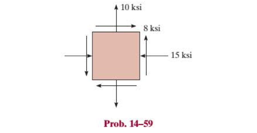
Chapter 14.4, Problem 59P
Determine (a) the principal stresses and (b) the maximum in-plane shear stress and average normal stress. Specify the orientation of the element in each case.
Expert Solution & Answer
Want to see the full answer?
Check out a sample textbook solution
Students have asked these similar questions
A piston–cylinder device contains 50 kg of water at 250 kPa and 25°C. The cross-sectional area of the piston is 0.1 m2. Heat is now transferred to the water, causing part of it to evaporate and expand. When the volume reaches 0.26 m3, the piston reaches a linear spring whose spring constant is 100 kN/m. More heat is transferred to the water until the piston rises 20 cm more.
NOTE: This is a multi-part question. Once an answer is submitted, you will be unable to return to this part.
Determine the work done during this process.
The work done during this process is kJ.
A 4-m × 5-m × 7-m room is heated by the radiator of a steam-heating system. The steam radiator transfers heat at a rate of 10,000 kJ/h, and a 100-W fan is used to distribute the warm air in the room. The rate of heat loss from the room is estimated to be about 5000 kJ/h. If the initial temperature of the room air is 10°C, determine how long it will take for the air temperature to rise to 25°C. Assume constant specific heats at room temperature. The gas constant of air is R = 0.287 kPa·m3/kg·K (Table A-1). Also, cv = 0.718 kJ/kg·K for air at room temperature (Table A-2).
Steam enters the radiator system through an inlet outside the room and leaves the system through an outlet on the same side of the room. The fan is labeled as W sub p w. The heat is given off by the whole system consisting of room, radiator and fan at the rate of 5000 kilojoules per hour.
It will take 831 Numeric ResponseEdit Unavailable. 831 incorrect.s for the air temperature to rise to 25°C.
A piston–cylinder device contains 50 kg of water at 250 kPa and 25°C. The cross-sectional area of the piston is 0.1 m2. Heat is now transferred to the water, causing part of it to evaporate and expand. When the volume reaches 0.26 m3, the piston reaches a linear spring whose spring constant is 100 kN/m. More heat is transferred to the water until the piston rises 20 cm more.
NOTE: This is a multi-part question. Once an answer is submitted, you will be unable to return to this part.
Determine the final pressure and temperature.
The final pressure is kPa.
The final temperature is ºC.
Find the work done during the process
Chapter 14 Solutions
Statics and Mechanics of Materials (5th Edition)
Ch. 14.3 - In each ease, the state of stress x, y, xy...Ch. 14.3 - Given the state of stress shown on the element,...Ch. 14.3 - Determine the normal stress and shear stress...Ch. 14.3 - Prob. 2FPCh. 14.3 - Determine the equivalent state of stress on an...Ch. 14.3 - Prob. 4FPCh. 14.3 - The beam is subjected to the load at its end....Ch. 14.3 - Prob. 6FPCh. 14.3 - Prove that the sum of the normal stresses x+y=x+y...Ch. 14.3 - Determine the stress components acting on the...
Ch. 14.3 - Determine the stress components acting on the...Ch. 14.3 - Determine the normal stress and shear stress...Ch. 14.3 - Determine the normal stress and shear stress...Ch. 14.3 - Prob. 6PCh. 14.3 - Prob. 7PCh. 14.3 - Determine the stress components acting on the...Ch. 14.3 - Determine the stress components acting on the...Ch. 14.3 - Determine the stress components acting on the...Ch. 14.3 - Determine the equivalent state of stress on an...Ch. 14.3 - Prob. 12PCh. 14.3 - Determine the stress components acting on the...Ch. 14.3 - Determine (a) the principal stresses and (b) the...Ch. 14.3 - Prob. 15PCh. 14.3 - Prob. 16PCh. 14.3 - Prob. 17PCh. 14.3 - Prob. 18PCh. 14.3 - Prob. 19PCh. 14.3 - Prob. 20PCh. 14.3 - Prob. 21PCh. 14.3 - The state of stress at a point in a member is...Ch. 14.3 - The wood beam is subjected to a load of 12 kN. If...Ch. 14.3 - Prob. 24PCh. 14.3 - The internal loadings at a section of the beam are...Ch. 14.3 - The internal loadings at a section of the beam are...Ch. 14.3 - Prob. 27PCh. 14.3 - Prob. 28PCh. 14.3 - The beam has a rectangular cross section and is...Ch. 14.3 - A paper tube is formed by rolling a cardboard...Ch. 14.3 - Prob. 31PCh. 14.3 - The 2-in.-diameter drive shaft AB on the...Ch. 14.3 - Determine the principal stresses in the...Ch. 14.3 - The internal loadings at a cross section through...Ch. 14.3 - The internal loadings at a cross section through...Ch. 14.3 - Prob. 36PCh. 14.3 - The steel pipe has an inner diameter of 2.75 in....Ch. 14.3 - Prob. 38PCh. 14.3 - The wide-flange beam is subjected to the 50-kN...Ch. 14.3 - Prob. 40PCh. 14.3 - The box beam is subjected to the 26-kN force that...Ch. 14.3 - The box beam is subjected to the 26-kN force that...Ch. 14.4 - Use Mohrs circle to determine the normal stress...Ch. 14.4 - Prob. 8FPCh. 14.4 - Prob. 9FPCh. 14.4 - Prob. 10FPCh. 14.4 - Prob. 11FPCh. 14.4 - Prob. 12FPCh. 14.4 - Solve Prob. 142 using Mohrs circle. 14-2.Determine...Ch. 14.4 - Solve Prob. 143 using Mohrs circle. 143.Determine...Ch. 14.4 - Determine the stress components acting on the...Ch. 14.4 - Solve Prob. 1410 using Mohrs circle. 149.Determine...Ch. 14.4 - Solve Prob. 1415 using Mohrs circle. 1415.The...Ch. 14.4 - Solve Prob. 1416 using Mohrs circle....Ch. 14.4 - Prob. 49PCh. 14.4 - Determine (a) the principal stresses and (b) the...Ch. 14.4 - Determine (a) the principal stresses and (b) the...Ch. 14.4 - Determine the equivalent state of stress if an...Ch. 14.4 - Draw Mohrs circle that describes each of the...Ch. 14.4 - Draw Mohrs circle that describes each of the...Ch. 14.4 - Determine (a) the principal stresses and (b) the...Ch. 14.4 - Determine (a) the principal stress and (b) the...Ch. 14.4 - Determine (a) the principal stresses and (b) the...Ch. 14.4 - Determine (a) the principal stresses and (b) the...Ch. 14.4 - Determine (a) the principal stresses and (b) the...Ch. 14.4 - Prob. 60PCh. 14.4 - The grains of wood in the board make an angle of...Ch. 14.4 - The post is fixed supported at its base and a...Ch. 14.4 - Determine the principal stresses, the maximum...Ch. 14.4 - The thin-walled pipe has an inner diameter of 0.5...Ch. 14.4 - The frame supports the triangular distributed load...Ch. 14.4 - The frame supports the triangular distributed load...Ch. 14.4 - Prob. 67PCh. 14.4 - The pedal crank for a bicycle has the cross...Ch. 14.4 - A spherical pressure vessel has an inner radius of...Ch. 14.4 - The cylindrical pressure vessel has an inner...Ch. 14.4 - Prob. 71PCh. 14.4 - Determine the principal stress at point D, which...Ch. 14.4 - If the box wrench is subjected to the 50 lb force,...Ch. 14.4 - If the box wrench is subjected to the 50-lb force,...Ch. 14.4 - Prob. 75PCh. 14.5 - Draw the three Mohrs circles that describe each of...Ch. 14.5 - Draw the three Mohrs circles that describe the...Ch. 14.5 - Draw the three Mohrs circles that describe the...Ch. 14.5 - Determine the principal stresses and the absolute...Ch. 14.5 - Prob. 80PCh. 14.5 - Prob. 81PCh. 14.5 - Prob. 82PCh. 14.8 - Prove that the sum of the normal strains in...Ch. 14.8 - The state of strain at the point on the arm has...Ch. 14.8 - The state of strain at the point on the pin leaf...Ch. 14.8 - The state of strain at the point on the pin leaf...Ch. 14.8 - Prob. 88PCh. 14.8 - The state of strain at a point on the bracket has...Ch. 14.8 - Prob. 90PCh. 14.8 - Prob. 91PCh. 14.8 - Prob. 92PCh. 14.8 - Prob. 93PCh. 14.8 - Prob. 94PCh. 14.8 - Prob. 95PCh. 14.8 - Prob. 96PCh. 14.8 - Prob. 97PCh. 14.8 - The state of strain on the element has components...Ch. 14.8 - Solve Prob. 1486 using Mohrs circle. 1486.The...Ch. 14.8 - Solve Prob. 1487 using Mohrs circle. 1486.The...Ch. 14.8 - Solve Prob. 1488 using Mohrs circle. 1488.The...Ch. 14.8 - Solve Prob. 1491 using Mohrs circle. 1491.The...Ch. 14.8 - Solve Prob. 1490 using Mohrs circle. 1489.The...Ch. 14.11 - The strain at point A on the bracket has...Ch. 14.11 - The strain at point A on a beam has components...Ch. 14.11 - The strain at point A on the pressure-vessel wall...Ch. 14.11 - The 45 strain rosette is mounted on the surface of...Ch. 14.11 - Prob. 109PCh. 14.11 - Use Hookes law, Eq. 1432, to develop the strain...Ch. 14.11 - Prob. 111PCh. 14.11 - A rod has a radius of 10 mm. If it is subjected to...Ch. 14.11 - The polyvinyl chloride bar is subjected to an...Ch. 14.11 - The polyvinyl chloride bar is subjected to an...Ch. 14.11 - The spherical pressure vessel has an inner...Ch. 14.11 - Determine the bulk modulus for each of the...Ch. 14.11 - The strain gage is placed on the surface of the...Ch. 14.11 - The principal strains at a point on the aluminum...Ch. 14.11 - Prob. 119PCh. 14.11 - Prob. 120PCh. 14.11 - The cube of aluminum is subjected to the three...Ch. 14.11 - The principal strains at a point on the aluminum...Ch. 14.11 - A uniform edge load of 500 lb/in. and 350 lb/in....Ch. 14.11 - Prob. 124PCh. 14 - The steel pipe has an inner diameter of 2.75 in....Ch. 14 - Prob. 2RPCh. 14 - Prob. 3RPCh. 14 - The crane is used to support the 350-lb load....Ch. 14 - In the case of plane stress, where the in-plane...Ch. 14 - The plate is made of material having a modulus of...Ch. 14 - If the material is graphite for which Eg = 800 ksi...Ch. 14 - A single strain gage, placed in the vertical plane...Ch. 14 - The 60 strain rosette is mounted on a beam. The...
Knowledge Booster


Learn more about
Need a deep-dive on the concept behind this application? Look no further. Learn more about this topic, mechanical-engineering and related others by exploring similar questions and additional content below.Similar questions
- A garden hose attached with a nozzle is used to fill a 20-gal bucket. The inner diameter of the hose is 1 in and it reduces to 0.53 in at the nozzle exit. The average velocity in the hose is 8 ft/s and the density of water is 62.4 lbm/ft3. NOTE: This is a multi-part question. Once an answer is submitted, you will be unable to return to this part. Determine the volume and mass flow rates of water through the hose. The volume flow rate of water through the hose is ft3/s. The mass flow rate of water through the hose is lbm/s. The change in time? What is the exit velocity?arrow_forwardA 23-ft3 rigid tank initially contains saturated refrigerant-134a vapor at 160 psia. As a result of heat transfer from the refrigerant, the pressure drops to 50 psia. NOTE: This is a multi-part question. Once an answer is submitted, you will be unable to return to this part. Determine the final temperature. Use data from refrigerant tables. The final temperature is ºF.arrow_forwardA 23-ft3 rigid tank initially contains saturated refrigerant-134a vapor at 160 psia. As a result of heat transfer from the refrigerant, the pressure drops to 50 psia. NOTE: This is a multi-part question. Once an answer is submitted, you will be unable to return to this part. Determine the heat transfer. The heat transfer is Btu.arrow_forward
- The shaft shown in the figure below is subjected to axial loads as illustrated. The diameters of segments AB, BC, and CD are 20mm, 25mm, and 15mm, respectively. If the modulus of elasticity of the material is 610 MPa. Determine the change of A to D lengtharrow_forwardDetermine the final pressure and temperature. The final pressure is kPa. The final temperature is ºC.arrow_forwardAir enters the 1-m2 inlet of an aircraft engine at 100 kPa and 20°C with a velocity of 184 m/s. Determine the volume flow rate, in m3/s, at the engine’s inlet and the mass flow rate, in kg/s, at the engine’s exit. The gas constant of air is R = 0.287 kPa·m3/kg·K. The volume flow rate at the engine’s inlet m3/s. The mass flow rate at the engine’s exit is kg/s.arrow_forward
- The ventilating fan of the bathroom of a building has a volume flow rate of 33 L/s and runs continuously. If the density of air inside is 1.20 kg/m3, determine the mass of air vented out in one day. The mass of air is kg.arrow_forwardA steady-flow compressor is used to compress helium from 15 psia and 70°F at the inlet to 200 psia and 600°F at the outlet. The outlet area and velocity are 0.01 ft2 and 100 ft/s, respectively, and the inlet velocity is 53 ft/s. Determine the mass flow rate and the inlet area. The gas constant of helium is R = 2.6809 psia·ft3/lbm·R. The mass flow rate is lbm/s. The inlet area is ft2.arrow_forward1. The maximum and minimum stresses as well as the shear stress seen subjected the piece in plane A-A. Assume it is a cylinder with a diameter of 12.7mm 2. Draw the Mohr circle for the stress state using software. 3. Selection of the material for the prosthesis, which must be analyzed from the point of safety and cost view.arrow_forward
arrow_back_ios
SEE MORE QUESTIONS
arrow_forward_ios
Recommended textbooks for you
 Elements Of ElectromagneticsMechanical EngineeringISBN:9780190698614Author:Sadiku, Matthew N. O.Publisher:Oxford University Press
 Mechanics of Materials (10th Edition)Mechanical EngineeringISBN:9780134319650Author:Russell C. HibbelerPublisher:PEARSON
 Thermodynamics: An Engineering ApproachMechanical EngineeringISBN:9781259822674Author:Yunus A. Cengel Dr., Michael A. BolesPublisher:McGraw-Hill Education
 Control Systems EngineeringMechanical EngineeringISBN:9781118170519Author:Norman S. NisePublisher:WILEY
 Mechanics of Materials (MindTap Course List)Mechanical EngineeringISBN:9781337093347Author:Barry J. Goodno, James M. GerePublisher:Cengage Learning
 Engineering Mechanics: StaticsMechanical EngineeringISBN:9781118807330Author:James L. Meriam, L. G. Kraige, J. N. BoltonPublisher:WILEY
Elements Of Electromagnetics
Mechanical Engineering
ISBN:9780190698614
Author:Sadiku, Matthew N. O.
Publisher:Oxford University Press
Mechanics of Materials (10th Edition)
Mechanical Engineering
ISBN:9780134319650
Author:Russell C. Hibbeler
Publisher:PEARSON
Thermodynamics: An Engineering Approach
Mechanical Engineering
ISBN:9781259822674
Author:Yunus A. Cengel Dr., Michael A. Boles
Publisher:McGraw-Hill Education
Control Systems Engineering
Mechanical Engineering
ISBN:9781118170519
Author:Norman S. Nise
Publisher:WILEY
Mechanics of Materials (MindTap Course List)
Mechanical Engineering
ISBN:9781337093347
Author:Barry J. Goodno, James M. Gere
Publisher:Cengage Learning
Engineering Mechanics: Statics
Mechanical Engineering
ISBN:9781118807330
Author:James L. Meriam, L. G. Kraige, J. N. Bolton
Publisher:WILEY
Understanding Stress Transformation and Mohr's Circle; Author: The Efficient Engineer;https://www.youtube.com/watch?v=_DH3546mSCM;License: Standard youtube license