
Videos
(a)
Design a circuit which produces a transfer function of
(a)
Explanation of Solution
Given data:
The given transfer function is,
Calculation:
The transfer function of the circuit is,
The above transfer function has a zero at
The Figure 14.39 (b) in the textbook, that shows a cascade two stages of the circuit with a zero at
For a single zero,
Substitute
Consider the value of
Substitute
Transfer function:
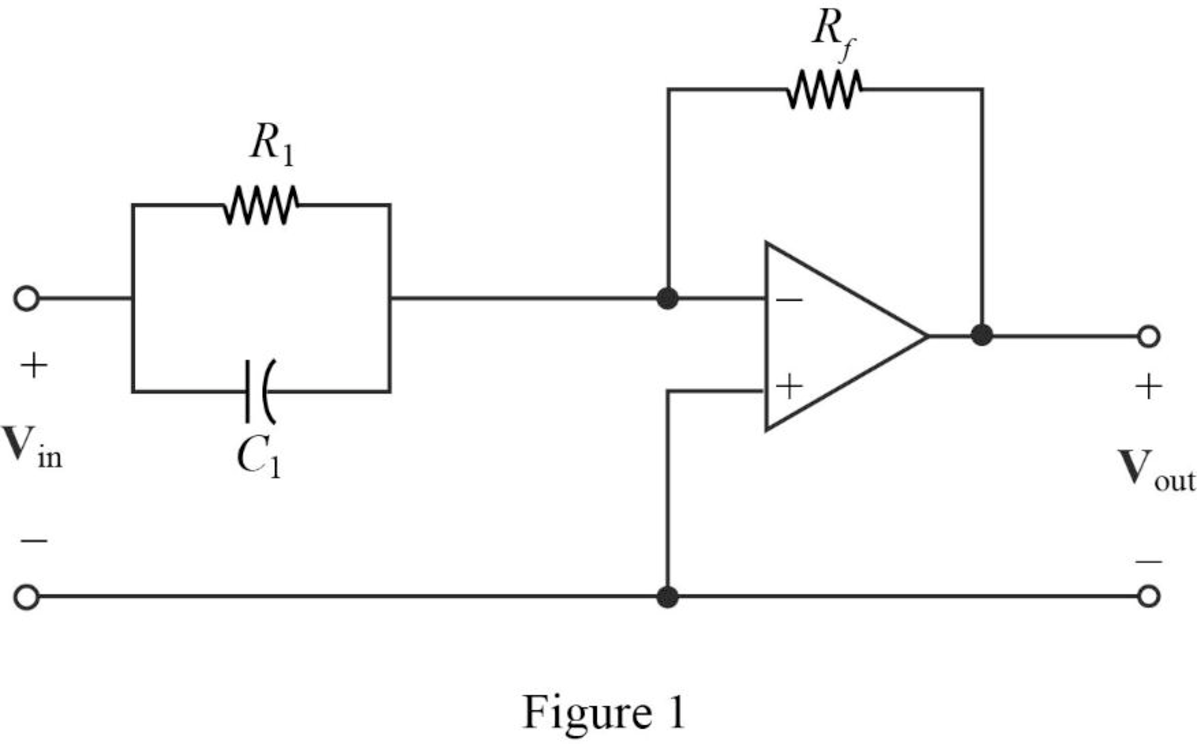
The input impedance of the cascaded circuit in Figure 1 is,
Then, write the Formula for the transfer function for the cascaded two stage amplifier.
Substitute
Thus, the transfer function for
Substitute 1 for
Completing the design by letting
If the input will be inverted, add an inverting amplifier with gain of 1 to provide the transfer function as follows.
Thus, the final design of the circuit is,
Conclusion:
Thus, a circuit is designed which produces a transfer function of
(b)
Design a circuit which produces a transfer function of
(b)
Explanation of Solution
Given data:
The given transfer function is,
Calculation:
The transfer function of the circuit is,
The above transfer function has pole at
The Figure 14.39 (a) in the textbook, that shows a cascade two stages of the circuit with pole at
For pole
Substitute
Let arbitrarily consider
Substitute
Transfer function:
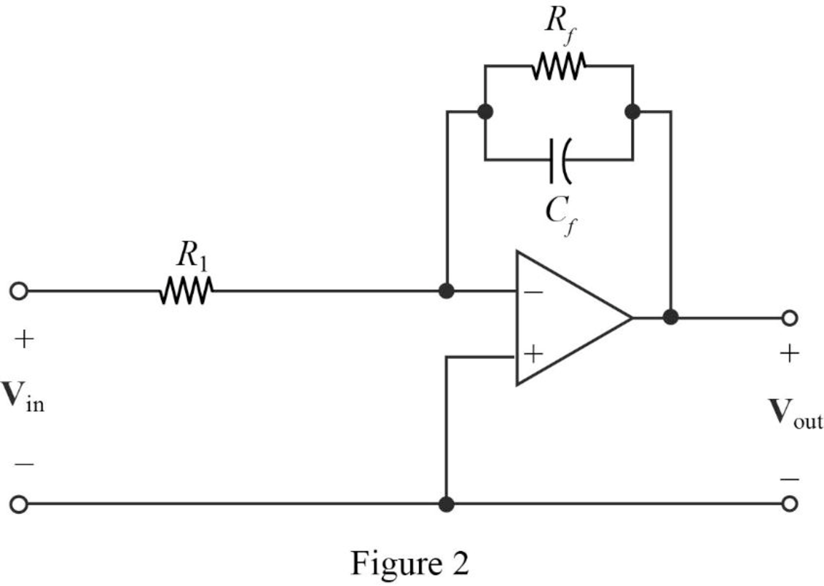
Find the feedback impedance of the cascaded circuit in Figure 2.
Write the formula for the transfer function of the cascaded circuit in Figure 2 as follows
Substitute
Therefore, consider the transfer function
Substitute 1 for
Completing the design by letting
If the input will be inverted, add an inverting amplifier with gain of 1 to provide the transfer function as follows.
Thus, the final design of the circuit is,
Conclusion:
Thus, a circuit is designed which produces a transfer function of
(c)
Design a circuit which produces a transfer function of
(c)
Explanation of Solution
Given data:
The given transfer function is,
Calculation:
The transfer function of the circuit is,
For the above transfer function, it has a zero at
Refer to Figure 1 in Part (a), that shows a cascade two stages of the circuit with a zero at
For a single zero,
Substitute
Let arbitrarily consider
Substitute
Consider the same circuit shown in Figure 1 and the transfer function as in a cascaded circuit,
Substitute 1 for
Completing the design by letting
Thus, the final design of the circuit is,
The given transfer function has a pole at
Refer to Figure 2 in Part (b), that shows a cascade two stages of the circuit with pole at
For pole
Substitute
Let arbitrarily consider
Substitute
The above equation becomes,
Consider the same circuit shown in Figure 2 and the transfer function as in a cascaded circuit,
Substitute 2 for
Completing the design by letting
Thus, the final design of the circuit is,
Therefore, the overall transfer function of the cascaded circuit is,
Substitute
Conclusion:
Thus, a circuit is designed which produces a transfer function of
Want to see more full solutions like this?
Chapter 14 Solutions
Engineering Circuit Analysis


- 2. What is the total impedance Zt of your designed circuit? Represent your result in cartesian form NOTE: use j to represent sqare root Zt=arrow_forwardAn electric resistance space heater is designed such that it resembles a rectangular box 55 cm high, 75 cm long, and 20 cm wide filled with 45 kg of oil. The heater is to be placed against a wall, and thus heat transfer from its back surface is negligible. The surface temperature of the heater is not to exceed 75°C in a room at 25°C for safety considerations. The emissivity of the outer surface of the heater is 0.8 and the average temperature of the ceiling and wall surfaces is the same as the room air temperature. The properties of air at 1 atm and the film temperature are: k = 0.02753 W/m-°C, v=1.798 x 10⁻⁵ m²/s, Pr = 0.7228, and ẞ= 0.003096K-1 Wall T₁ =75°C Oil € = 0.8 Electric heater Heating element Disregarding heat transfer from the bottom and top surfaces of the heater in anticipation that the top surface will be used as a shelf, determine the power rating of the heater in W. The power rating of the heater is W.arrow_forwardcircuit 2arrow_forward
- Suppose you have 8 LED's connected to port-B (Bo-B7) of PIC16F877A and one switch connected to port-D (Do) as shown in figure below. Write a program code that performs a nibble (4-bits) toggling: if the switch is released then LED's (Bo to B3) are OFF and LED's (B4 to B7) are ON, while if the switch is pressed then LED's (Bo to B3) are ON and LED's (B4 to B7) are OFF. Use 300ms delay for each case with 4MHz frequency. 13 14 22 NATHON 20 U1 OSC1/CLKIN U2 33 REOINT 20 34 OSC2/CLKOUT 19 RB1 35 3 18 RB2 RADIANO debt0RB3PGM 30 4 17 37 5 10 RA1/AN1 RB4 38 RA2/ANZ/VREF-/CVREF 15 RB5 39097 RA3/AN3VREF RB6/PGC 7 14 40 RA4/TOCK/C1OUT 13 RB7/PGO RAS/ANA/SS/CZOUT 15 RCO/T1OSO/TICKI 10 11 REQIANS/RD 18 RC1/T10S/CCP2 17 10 RE1/AN/WR REZ/ANTICS MCLR/Vpp/THV RC2/CCP1 LED-BARGRAPH-RED RC3/SCK/SCL RC4/SDUSDA RC5/SDO Eng of ROSTX/CX RC7/RX/DT RDO/PSPO RD1/PSP1 RD2PSP2 RO3/PSP3 RD4/PSP4 ROS/PSP5 RD6/PSP6 RD7/PSP7 PIC16F877A +5V R1 100Rarrow_forwardWrite a PIC16F877A program that flash ON the 8-LED's connected to port-B by using two switches connected to port-D (Do & D₁) as shown in figure below, according to the following scenarios: (Hint: Use 500ms delay for each case with 4MHz frequency) 1. When Do=1 then B₁,B3,B, are ON. 2. When Do 0 then Bo,B2,B4, B5, B6 are ON. 3. When D₁=1 then B4,B,,B6,B7 are ON. 4. When D₁-0 then Bo,B1,B2,B3 are ON. U1 5 33 OSC/CLION OSC2/CLKOUT ROOINT RB1 35 RB2 20 17 RACIANO RESPOM RATANT RAZIANZ/VREF-CVREF RBS RA3/AN3/VREF+ REPOC 39 14 40 RA4/TOCK C1OUT 13 RB7/PGO 12 RASIAN/SCOUT 15 ROOT1050/TICK +5V REGIANERD REVANDVIR REZANTICS RCMT10SUCCP2 17 RC2/CCP1 LED-BARGRAPH-RED RC3SCHISCL 23 --- MCUANTV RC4/SOSDA 24 RCS/SDO RCB/TICK RC7/RXDT 25 ROOPSPO RDMPSP1 RD2PSF2 RO3PSP3 RD4PSP4 RDSPSPS PIC16F877A ROOPSP RO7/PSP7 R2 R1 100R 100Rarrow_forwardQuestion 5 The following data were obtained from testing a 48-kVA 240/4800 V step up transformer. Open-circuit test Short-circuit test Voltage (V) 240 150 Current (I) 2 10 Power (W) 120 600 Determine the equivalent circuit of the transformer as viewed from the primary side. Ans: Rc = 480 ohm, Xm = 123.94 ohm, Reqp = 0.015 ohm, Xeqp = 0.034 ohmarrow_forward
- From the following mass-spring system, obtain its transfer function and pole-zero wwwwwwww wwww diagram in MATLAB. Analyze how stability varies when entering values. wwwww (4)x1 ▷ x(t) M f(t) B f(t) is the input variable and x(t) is the controlled variable.arrow_forwardR2 L3 C5 BRF_OUT HH Sine_OUT 100 1m 100n C3 C4 100n 100n Figure 9. Square to sine waveform converter circuit How do we make sense of this? First, we note that R2 and C3 form a first order low pass filter and L3 and C4 form another low pass filter. Both low pass filters have been set at the same cutoff frequency. The combination of both form a two stage filter to remove the high frequency content present in the DAB signal. Capacitor C5 is used to remove any residual DC offset in the signal. But let's just deal with the AC steady state response, which means that you don't need to know any of these details, and then can conveniently treat this circuit as a blackbox. What is the theoretical cutoff frequency for the RC and LC filters shown in Figure 9? Answer to within 1% accuracy. (a) RC Filter cutoff frequency (f 1) = kHzarrow_forwardFor the following steady-state AC circuit, find the complex output voltage, VO, shown in the diagram. Write the answer in polar form (angles in degrees), accurate within 1%. L1=0.7H, L2=5H, C=14F, R=0.60, and w=0.7 rad/s L1 m Vo R Vs 5/30°V Answer: ய ww L2 23arrow_forward
- Please draw logic circuitarrow_forwardA 220-volt, 20-horsepower compound motor (long shunt, Figure 21–16A) has an armature resistance of 0.25 ohm, series field resistance of 0.19 ohm, and shunt field resistance of 33 ohms. a. Calculate the current taken by the motor at the instant of starting if it is con-nected directly to the 220-volt line. b. Calculate the current when the motor is running if the armature is developing 184 volts counter-emf.arrow_forwardDesign a modulo-11 ripple (asynchronous) up-counter with negative edge-triggered T flip-flops and draw the corresponding logic circuit. (I)Build the state diagram and extract the state table (II)Draw the logic circuit (III)What is the maximum modulus of the counter?arrow_forward
 Introductory Circuit Analysis (13th Edition)Electrical EngineeringISBN:9780133923605Author:Robert L. BoylestadPublisher:PEARSON
 Delmar's Standard Textbook Of ElectricityElectrical EngineeringISBN:9781337900348Author:Stephen L. HermanPublisher:Cengage Learning
 Programmable Logic ControllersElectrical EngineeringISBN:9780073373843Author:Frank D. PetruzellaPublisher:McGraw-Hill Education
 Fundamentals of Electric CircuitsElectrical EngineeringISBN:9780078028229Author:Charles K Alexander, Matthew SadikuPublisher:McGraw-Hill Education
 Electric Circuits. (11th Edition)Electrical EngineeringISBN:9780134746968Author:James W. Nilsson, Susan RiedelPublisher:PEARSON
 Engineering ElectromagneticsElectrical EngineeringISBN:9780078028151Author:Hayt, William H. (william Hart), Jr, BUCK, John A.Publisher:Mcgraw-hill Education,