
Concept explainers
Videos
(a)
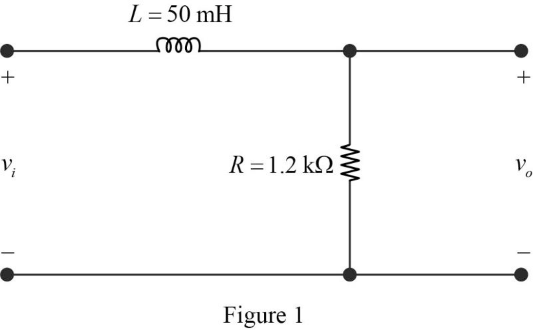
Find the value of the cutoff frequency in hertz for the RL low-pass filter shown in given figure.
(a)
Answer to Problem 1P
The value of the cutoff frequency
Explanation of Solution
Given data:
Refer to given figure in the textbook.
Formula used:
Write the expression to calculate the angular cutoff frequency.
Here,
Write the expression to calculate the cutoff frequency of the RL low-pass filter.
Here,
Calculation:
The given filter circuit is drawn as Figure 1.
Substitute
Simplify the above equation to find
Substitute
Rearrange the above equation to find
Conclusion:
Thus, the value of the cutoff frequency
(b)
Find the value of the transfer function
(b)
Answer to Problem 1P
The value of the transfer function
Explanation of Solution
Formula used:
Write the expression to calculate the impedance of the passive elements resistor and inductor.
Calculation:
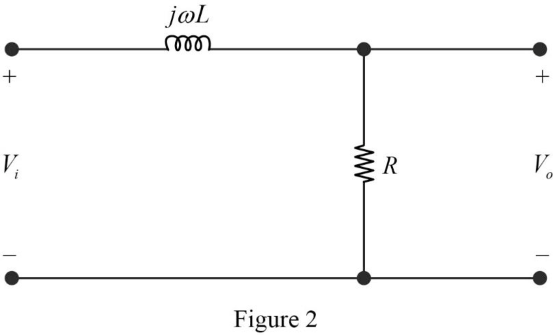
The impedance circuit of the Figure 1 is drawn as Figure 2 using the equations (3) and (4).
Apply voltage division rule on Figure 2 to find
Rearrange the above equation to find
Substitute the equation (2) in above equation to find
Write the expression to calculate the transfer function of the circuit in Figure 2.
Substitute
Substitute
Substitute
Substitute
Substitute
Substitute
Substitute
Substitute
Conclusion:
Thus, the value of the transfer function
(c)
Find the steady state expression for the output voltage
(c)
Answer to Problem 1P
The steady state expression for the output voltage
Explanation of Solution
Given data:
The input voltage is,
Calculation:
From part (b),
Rearrange the above equation to find
The time domain expression for the above equation is written as,
Substitute
Substitute
Substitute
Simplify the above equation to find
Substitute
Substitute
Simplify the above equation to find
Substitute
Substitute
Simplify the above equation to find
Conclusion:
Thus, the steady state expression for the output voltage
Want to see more full solutions like this?
Chapter 14 Solutions
Electric Circuits, Global Edition


- Don't use ai to answer I will report you answerarrow_forwardDon't use ai to answer I will report you answerarrow_forwardQ3/A unity-feedback system with the forward transfer function G(S)= K S(S+7) is operating with a closed-loop step response that has 15% overshoot. Do the following: a. Evaluate the steady-state error for a unit ramp input. b. Design a lag compensator to improve the steady-state error by a factor of 20 to get a new dominant closed-loop poles S-3.4+ j5.63. place the pole of the lag compensator at s=-0.01 c. Design a lag compensator using OP amp if R1= 100KS2 R2=10 KS2 and R3= 10Karrow_forward
- Q2: (33 Marks) Design FBD for manufacturing system where a conveyor belt is used to move a cart through a tunnel for processing. The process begins when a worker presses a start push button located at the start of the conveyor. Once the start push button is pressed, the cart moves forward along the conveyor belt and enters the tunnel. When the cart reaches the end of the tunnel, it stops automatically and remains in place for 10-minutes to complete a required operation, such as cooling or drying. After the 10-minute delay, the cart automatically returns to the starting point where the worker is stationed. The system then waits for the worker to press the start push button again, at which point the process is repeated. Start PBO Stop PBO LSI 0 LS 2 Motorarrow_forward1. Find the resolution, current and output voltage for a binary weighted resistor DAC of (applied binary word is (locoj), the resistor values R = 12 kQ, Rf = 6 k2 and VR = 12 V. 2. Convert the following 5-bit digital values (ble 10) to analog, using the R-2R ladder. Assume that the Vs = 10 V, R = Rf = 7 ksarrow_forwardK Q4/ For the unity-feedback system where G(s) = do the following: a. Plot the Nyquist diagram. (S+2)(S+4)(S+6) b. Use your Nyquist diagram to find the range of gain, K, for stabilityarrow_forward
- Q6/ Answer (two) of the following question A For the following G(s), find analytical expressions for the magnitude and phase response and make a plot of the logmagnitude and the phase, using log-frequency in rad/s as the ordinate. G(S)=- 1 (S+2)(S+4)arrow_forwardQ5 Given the system of Figure below, with dominant poles -5.415 t/10.57. design a PID controller so that the system can operate with a peak time that is two-thirds that of the uncompensated system at 20% overshoot to get and with zero steady-state error for a step input and KV= 5.7163sec and final K=4.6. R(s) + E(s) K(s + 8) (s+3)(x+6)(s + 10) C(s)arrow_forward".I need the correct answers with explanations" Answer True or False, then correct errors or explain if any: 1. The term pole in filter terminology refers to the feedback circuit. 2, A voltage shunt feedback with Ai-10, A-20, p 0.45, then Aif will be 1. 3. The integrator Op-Amp circuit can be used to produce square waves. 4. The equivalent circuit of the crystal oscillator is series and parallel (R, C) components. 5. The transistor in a class A power amplifier conducts for the entire input cycle. 6. Bypass capacitors in an amplifier determine the low and high-frequency responses. 7. The midrange voltage gain of an amplifier is 100. The input RC circuit has a lower critical frequency of 1 kHz. The actual voltage gain at f-100 Hz is 100. 8. The Bessel filter types produce almost ripple frequency response. 9. RC phase shift oscillators are based on both positive and negative feedback circuits. 10. In a high-pass filter, the roll-off region occurs above the critical frequency.arrow_forward
- ".I need the correct answers with explanations" Answer True or False and correct errors if found: Marks) 1. The LC oscillator circuits are used to operate in low and moderate frequencies. 2. The voltage series feedback can increase both input and output impedances. 3. A two-pole Sallen-Key high-pass filter contains one capacitor and two resistors. 4. The main feature of a crystal oscillator is the high frequency operation that operates with optoelectronic effect. 5. The max. efficiency of the class B power amplifier is 50%. 6. The Q-point must be centered on the load line for maximum class AB output signal swing. 7. The differentiator Op-Amp can convert the triangle waveform into sinewave. 8. Class AB power amplifier eliminates crossover distortion found in pure class A. 9. RC-phase shift oscillators are based on positive feedback circuits. 10. Bypass capacitors in an amplifier determine the low and high-frequency responses.arrow_forwardK Q2/A For the system G(s)= H(s)=1 9 (s+5)(s+2 )(s+5) a. Draw the Bode log-magnitude and phase plots. b. Find the range of K for stability from your Bode plots. c. Evaluate gain margia, phase margin, zero dB frequency, and 180° frequency from your Bode plots for K = 10,000.arrow_forwardPlease solve this question step by step handwritten solution and do not use ai or chat gpt pleasearrow_forward
 Introductory Circuit Analysis (13th Edition)Electrical EngineeringISBN:9780133923605Author:Robert L. BoylestadPublisher:PEARSON
 Delmar's Standard Textbook Of ElectricityElectrical EngineeringISBN:9781337900348Author:Stephen L. HermanPublisher:Cengage Learning
 Programmable Logic ControllersElectrical EngineeringISBN:9780073373843Author:Frank D. PetruzellaPublisher:McGraw-Hill Education
 Fundamentals of Electric CircuitsElectrical EngineeringISBN:9780078028229Author:Charles K Alexander, Matthew SadikuPublisher:McGraw-Hill Education
 Electric Circuits. (11th Edition)Electrical EngineeringISBN:9780134746968Author:James W. Nilsson, Susan RiedelPublisher:PEARSON
 Engineering ElectromagneticsElectrical EngineeringISBN:9780078028151Author:Hayt, William H. (william Hart), Jr, BUCK, John A.Publisher:Mcgraw-hill Education,