
Concept explainers
Videos
(a)
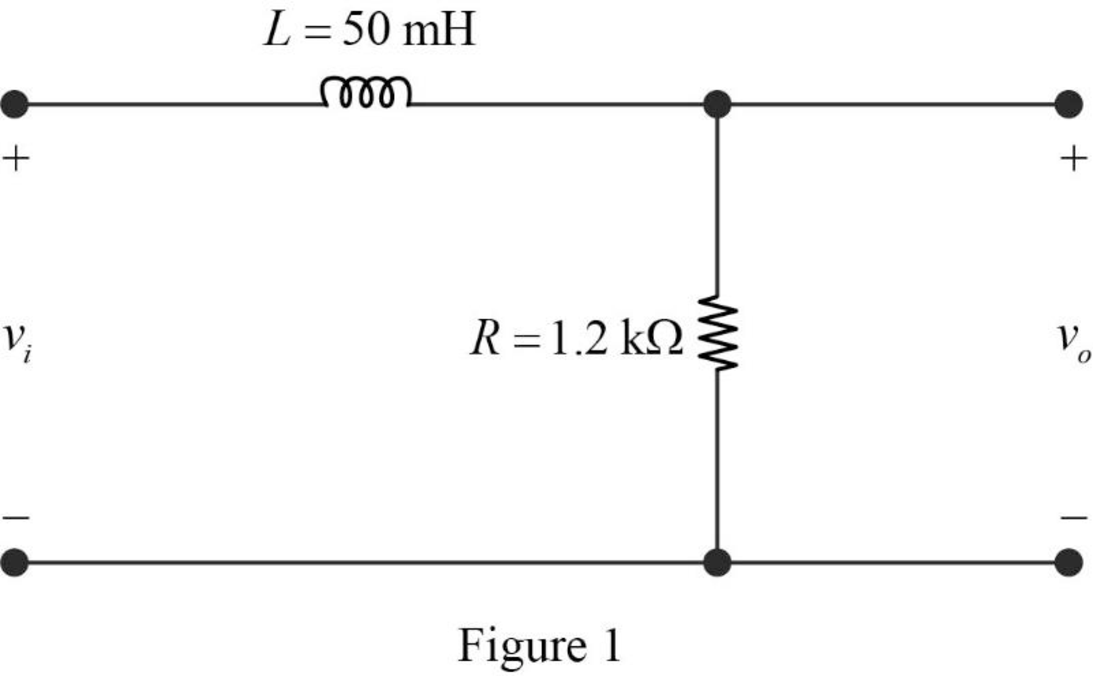
Find the value of the cutoff frequency in hertz for the RL low-pass filter shown in given figure.
(a)
Answer to Problem 1P
The value of the cutoff frequency
Explanation of Solution
Given data:
Refer to given figure in the textbook.
Formula used:
Write the expression to calculate the angular cutoff frequency.
Here,
Write the expression to calculate the cutoff frequency of the RL low-pass filter.
Here,
Calculation:
The given filter circuit is drawn as Figure 1.
Substitute
Simplify the above equation to find
Substitute
Rearrange the above equation to find
Conclusion:
Thus, the value of the cutoff frequency
(b)
Find the value of the transfer function
(b)
Answer to Problem 1P
The value of the transfer function
Explanation of Solution
Formula used:
Write the expression to calculate the impedance of the passive elements resistor and inductor.
Calculation:
The impedance circuit of the Figure 1 is drawn as Figure 2 using the equations (3) and (4).
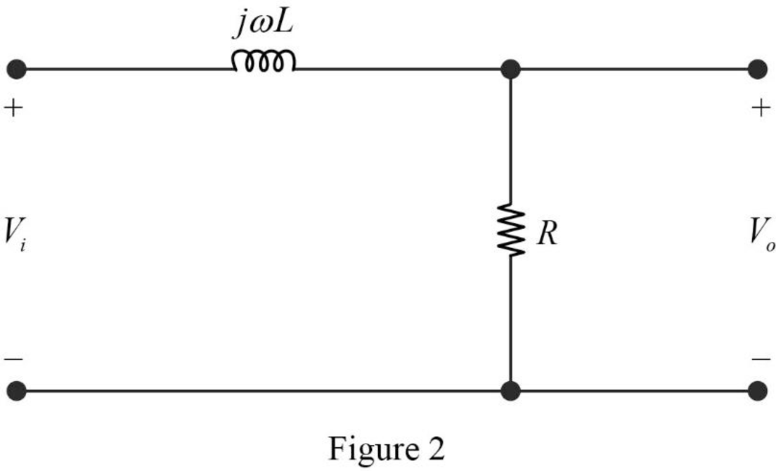
Apply voltage division rule on Figure 2 to find
Rearrange the above equation to find
Substitute the equation (2) in above equation to find
Write the expression to calculate the transfer function of the circuit in Figure 2.
Substitute
Substitute
Substitute
Substitute
Substitute
Substitute
Substitute
Substitute
Conclusion:
Thus, the value of the transfer function
(c)
Find the steady state expression for the output voltage
(c)
Answer to Problem 1P
The steady state expression for the output voltage
Explanation of Solution
Given data:
The input voltage is,
Calculation:
From part (b),
Rearrange the above equation to find
The time domain expression for the above equation is written as,
Substitute
Substitute
Substitute
Simplify the above equation to find
Substitute
Substitute
Simplify the above equation to find
Substitute
Substitute
Simplify the above equation to find
Conclusion:
Thus, the steady state expression for the output voltage
Want to see more full solutions like this?
Chapter 14 Solutions
Electric Circuits (10th Edition)


- Preliminary Laboratory (Prelab) Work Complete the following tasks in the space provided below for the circuit shown in Figure 2. 1. Use voltage division to compute the phasor voltages VR and Vc assuming nominal values of R = 1000[2], C = 0.01[u], and a cosinusoidal time-domain source voltage signal given by equation 5 below. Voltage division must be used to receive any credit. (10 points) equation (5) Vs(t) = VRMSCOS(ct + 0) = 5cos(@t + 0) = 5cos(62832t + 0) = 5cos(62832t) [V] =VRMSCOS(2лft + 0) = 5cos[2л(10000)t + 0] = 5cos[2л(10000)t] [V] 2. Compute the phasor current, Is. (3 points) 3. Calculate the complex power, S, active power, P, and reactive power, Q, for the circuit. (4 points) 4. Construct the phasor diagram for the circuit, and show mathematically that the phasor (vector) sum of the phasor voltages VR and Vc is equal to Vs. (3 points) Agilent 33210A (BECC4242) or Vs Keysight 33500B (BECC4261) Function Generators Is R w + VR Vc + + Zc V out =Vc Figure 2: RC circuit connected…arrow_forwardPlease explain in detail. My answer for the first question is 15/2. I am more confused about how to do the graphing part and figure how long it will take to reach its final value. Thank you, I will like this.arrow_forwardThis is the 3rd time i'm asking this. SOLVE THIS AND FIND V0 , the last answer i was given is -2V which is not even one of the listed options. the listed options are: 12V,4V,24V,6V. first answer given to me was 4V but after i simulated on ltspice albeit i'm not sure if i simulated correct i got a different answer and when i solved it myself i got a different answer. this is my last remaining question. PLEASE SOLVE CORRECTLY AND PROPERLY. NODAL ANALYSIS IS BEST TO USE HERE. IT IS AN IDEAL OP-AMP. SIMULATE USING LTSPICE AND GIVE ME FINAL ANSWER IF POSSIBLE AS THAT IS ALL I CARE ABOUT NOT THE PROCESS. THANK YOU. WILL UPVOTE CORRECT ANSWER, but downvote wrong answer.arrow_forward
- Find the exact value of V0. This question was already asked here and the answer was 4V i solved it myself and got a different answer and when i simulated it i also got a different answer.But i might be wrong. so please solve this for me and IF POSSIBLE simulate it so we can be 100% sure that the answer is correct as it's very important that i understand where i went wrong.arrow_forwardFind load flow Solution 1.2 20 Z12 = 0.01+jo.03 in Z₁4=0.02+0.04 и а 9.01+10.03 0.02+0.04 0.01+0.03 58-1 Vek 1.05 100 MVA Pe=230 MW 150 MW w 140 MW 01012 +0.035 80 M√ar 723=0.01+0.03 90 mvare Z34 = 0.012+ 10.035arrow_forwardSD = 100 MVA 1.12° 150mw ← 0.01+0.03 10.02 -0.04 Too M P = 250 MW 0.02+0.04 0.012 jo.03 $ (V3)=1.05 P.4 -03 = = 200 MW 212=0.01+10.03 Zzze 0.02 +10.04 214=0.02+10.04 Z34 = 0.012+10.03arrow_forward
- Choose the correct answer to the following questions: 1- What is the total power radiated in Watts for the power density W = a) 4π² b) 8m²/3 2- Fresnel zone is also called as sine W/m²? 3r² c) 4π²/3 d) 2π²/3 a) Near Field b) Far Field c) Electrostatic Field d) Reactive Field 3- The far-field distance at 900 MHz, if the maximum antenna dimension is 0.75 m is.... a) 3.375 m b) 3.5m c) 3.375 cm d) none 4- The antenna gain is on input power to antenna and on power due to ohmic losses. c) Independent, dependent d) a) Independent, independent b) Dependent, independent Dependent, dependent 5- If beam width of the antenna increases, then directivity. a) Decreases b) Increases c) Remains unchanged d) Depends on type of antennaarrow_forwardplease solve this and clarify each step. thanksarrow_forwardThe input reactance of 1/2 dipole with radius of 1/30 is given as shown in figure below, Assuming the wire of dipole is conductor 5.6*107 S/m, determine at f=1 GHz the a- Loss resistance, b- Radiation efficiency c- Reflection efficiency when the antenna is connected to T.L shown in the figure. Rr Ro= 50 2 Avg/4 RL -j100 [In(l/a) 1.5] tan(ẞ1)arrow_forward
- Find Zeq here. i already had one solution written to me but it's wrong. my main question is. i know that i do the parallel connection first so 2x2 / 2+2 = 1ohm but what i'm asking is since it's an open terminal is R3,2(parallel resistors) in series to R1? or should i first do R3,2 // to ZL and then add R1 in series? PLEASE READ THIS. and solve properly. EXPLAIN WHAT I ASKED PROPERLY. UPVOTE WILL BE GIVEN.arrow_forwardThe E-field pattern of an antenna, independent of o, varies as follows: E = 0 7100 0° ≤0≤45° 45° < 0 ≤ 90° 90° < 0 ≤ 180° (a) What is the directivity of this antenna? (b) What is the radiation resistance of the antenna at 200 m from it if the field is equal to 10 V/m (rms) for 0 = 0° at that distance and the terminal current is 5 A (rms)?arrow_forwardFind Zeq here. i already had one solution written to me but it's wrong. my main question is. i know that i do the parallel connection first so 2x2 / 2+2 = 1ohm but what i'm asking is since it's an open terminal is R3,2(parallel resistors) in series to R1? or should i first do R3,2 // to ZL and then add R1 in series? PLEASE READ THIS. and solve properly. EXPLAIN WHAT I ASKED PROPERLY. UPVOTE WILL BE GIVEN.arrow_forward
 Introductory Circuit Analysis (13th Edition)Electrical EngineeringISBN:9780133923605Author:Robert L. BoylestadPublisher:PEARSON
 Delmar's Standard Textbook Of ElectricityElectrical EngineeringISBN:9781337900348Author:Stephen L. HermanPublisher:Cengage Learning
 Programmable Logic ControllersElectrical EngineeringISBN:9780073373843Author:Frank D. PetruzellaPublisher:McGraw-Hill Education
 Fundamentals of Electric CircuitsElectrical EngineeringISBN:9780078028229Author:Charles K Alexander, Matthew SadikuPublisher:McGraw-Hill Education
 Electric Circuits. (11th Edition)Electrical EngineeringISBN:9780134746968Author:James W. Nilsson, Susan RiedelPublisher:PEARSON
 Engineering ElectromagneticsElectrical EngineeringISBN:9780078028151Author:Hayt, William H. (william Hart), Jr, BUCK, John A.Publisher:Mcgraw-hill Education,