
EBK STATICS AND MECHANICS OF MATERIALS
5th Edition
ISBN: 8220102955295
Author: HIBBELER
Publisher: PEARSON
expand_more
expand_more
format_list_bulleted
Concept explainers
Videos
Textbook Question
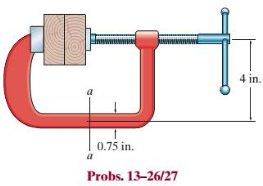
Chapter 13.2, Problem 26P
The screw of the clamp exerts a compressive force of 500 lb on the wood blocks. Determine the maximum normal stress along section a–a. The cross section is rectangular. 0.75 in. by 0.50 in.
Expert Solution & Answer
Want to see the full answer?
Check out a sample textbook solution
Students have asked these similar questions
Pearson eText
Study Area
Document Sharing
User Settings
mylabmastering.pearson.com
Access Pearson
P Pearson MyLab and Mastering
Problem 14.69
Part A
P Course Home
b Answered: HW_02.pdf EE 213-01 > Assignments HW_#...
1 of 8
Review
The 5-kg collar has a velocity of 7 m/s to the right when
it is at A. It then travels down along the smooth guide
shown in (Figure 1). The spring has an unstretched
length of 100 mm and B is located just before the end
of the curved portion of the rod.
Determine the speed of the collar when it reaches point B, which is located just before the end of the curved portion of the rod.
Express your answer to three significant figures and include the appropriate units.
Figure
1 of 1
με
v =
Value
Units
Submit
Request Answer
Part B
?
What is the normal force on the collar at this instant?
Express your answer to three significant figures and include the appropriate units.
☐
μÅ
?
N =
Value
Units
Submit
Request Answer
Provide Feedback
Next >
Pearson eText
Study Area
mylabmastering.pearson.com
Access Pearson
P Pearson MyLab and Mastering
Problem 15.106
P Course Home
b Answered: HW_02.pdf EE 213-01 > Assignments HW_#...
8 of 8
Document Sharing
User Settings
The two spheres A and B each have a mass of 400 g.
The spheres are fixed to the horizontal rods as shown in
(Figure 1) and their initial velocity is 2 m/s. The mass of
the supporting frame is negligible and it is free to rotate.
Neglect the size of the spheres.
Part A
If a couple moment of M = 0.3 N · m is applied to the frame, determine the speed of the spheres in 3 s.
Express your answer to three significant figures and include the appropriate units.
Figure
1 of 1
☐
?
v =
Value
Units
Units input for part A
Submit
Request Answer
Return to Assignment
Provide Feedback
■Review
Pearson eText
Study Area
Access Pearson
mylabmastering.pearson.com
P Pearson MyLab and Mastering
Problem 15.79
P Course Home
b Answered: HW_02.pdf EE 213-01 > Assignments HW_#...
6 of 8
>
Document Sharing
User Settings
The two disks A and B have a mass of 4 kg and 5 kg,
respectively. They collide with the initial velocities shown.
The coefficient of restitution is e = 0.65. Suppose that
(VA)1 = 6 m/s, (VB)1 = 8 m/s. (Figure 1)
Part A
Determine the magnitude of the velocity of A just after impact.
Express your answer to three significant figures and include the appropriate units.
Figure
1 of 1
μÅ
(VA)2 =
Value
Units
Submit
Request Answer
Part B
?
Review
Determine the angle between the x axis and the velocity of A just after impact, measured clockwise from the negative x axis.
Express your answer in degrees to three significant figures.
ΕΠΙ ΑΣΦ
vec
01
Submit
Request Answer
Part C
?
Determine the magnitude of the velocity of B just after impact.
Express your answer to three significant…
Chapter 13 Solutions
EBK STATICS AND MECHANICS OF MATERIALS
Ch. 13.1 - A spherical gas tank has an inner radius of r =...Ch. 13.1 - A pressurized spherical tank is made of...Ch. 13.1 - The thin-walled cylinder can be supported in one...Ch. 13.1 - Prob. 4PCh. 13.1 - Prob. 5PCh. 13.1 - Determine the maximum force P that can be exerted...Ch. 13.1 - Prob. 7PCh. 13.1 - The steel water pipe has an inner diameter of 12...Ch. 13.1 - The steel water pipe has an inner diameter of 12...Ch. 13.1 - The A-36-steel band is 2 in. wide and is secured...
Ch. 13.1 - The gas pipe line is supported every 20 ft by...Ch. 13.1 - Prob. 12PCh. 13.1 - An A-36-steel hoop has an inner diameter of 23.99...Ch. 13.1 - The ring, having the dimensions shown, is placed...Ch. 13.1 - Prob. 15PCh. 13.1 - Prob. 16PCh. 13.1 - Prob. 17PCh. 13.2 - In each case, determine the internal loadings that...Ch. 13.2 - The internal loadings act on the section. Show the...Ch. 13.2 - Determine the normal stress at comers A and B of...Ch. 13.2 - Determine the state of stress at point A on the...Ch. 13.2 - Determine the state of stress at point A on the...Ch. 13.2 - Determine the magnitude of the load P that will...Ch. 13.2 - Prob. 5FPCh. 13.2 - Determine the state of stress at point A on the...Ch. 13.2 - Determine the state of stress at point A on the...Ch. 13.2 - Determine the state of stress at point A on the...Ch. 13.2 - Determine the shortest distance d to the edge of...Ch. 13.2 - Determine the maximum distance d to the edge of...Ch. 13.2 - The plate has a thickness of 20 mm and the force P...Ch. 13.2 - If the load has a weight of 600 lb, determine the...Ch. 13.2 - The steel bracket is used to connect the ends of...Ch. 13.2 - Prob. 23PCh. 13.2 - The column is built up by gluing the two boards...Ch. 13.2 - Prob. 25PCh. 13.2 - The screw of the clamp exerts a compressive force...Ch. 13.2 - Prob. 27PCh. 13.2 - Prob. 28PCh. 13.2 - The joint is subjected to the force system shown....Ch. 13.2 - Prob. 30PCh. 13.2 - The 12-in.-diameter holt hook is subjected to the...Ch. 13.2 - Prob. 32PCh. 13.2 - Prob. 33PCh. 13.2 - Prob. 34PCh. 13.2 - Prob. 35PCh. 13.2 - The drill is jammed in the wall and is subjected...Ch. 13.2 - The drill is jammed in the wall and is subjected...Ch. 13.2 - The frame supports the distributed load shown....Ch. 13.2 - Prob. 39PCh. 13.2 - The rod has a diameter of 40 mm. If it is...Ch. 13.2 - The rod has a diameter of 40 mm. If it is...Ch. 13.2 - The beveled gear is subjected to the loads shown....Ch. 13.2 - The beveled gear is subjected to the loads shown....Ch. 13.2 - Determine the normal-stress developed at points A...Ch. 13.2 - Sketch the normal-stress distribution acting over...Ch. 13.2 - Prob. 46PCh. 13.2 - The solid rod is subjected to the loading shown....Ch. 13.2 - Prob. 48PCh. 13.2 - Prob. 49PCh. 13.2 - The C-frame is used in a riveting machine. If the...Ch. 13.2 - Prob. 51PCh. 13.2 - The uniform sign has a weight of 1500 lb and is...Ch. 13.2 - The uniform sign has a weight of 1500 lb and is...Ch. 13 - The post has a circular cross section of radius c....Ch. 13 - The 20-kg drum is suspended from the hook mounted...Ch. 13 - The 20-kg drum is suspended from the hook mounted...Ch. 13 - Prob. 4RPCh. 13 - If the cross section of the femur at section aa...Ch. 13 - Prob. 6RPCh. 13 - Prob. 7RPCh. 13 - Prob. 8RP
Knowledge Booster


Learn more about
Need a deep-dive on the concept behind this application? Look no further. Learn more about this topic, mechanical-engineering and related others by exploring similar questions and additional content below.Similar questions
- 40.00 30.00 100.00- 100.00 P = 1000 N A=167 d=140.00 100.00- -b 20.00 200.00 Weld Strength P = 273 N/mm^2 Electrod E60 Safety factor S₁ = 3 Force P = 1000 N Using by SOLIDWORKSarrow_forwardWhat are the reaction forces in A and B?arrow_forwardPearson eText Study Area Access Pearson mylabmastering.pearson.com P Pearson MyLab and Mastering Problem 15.6 P Course Home b Answered: HW_02.pdf EE 213-01 > Assignments HW_#... 3 of 8 ■ Review Document Sharing User Settings The jet plane has a mass of 250 Mg and a horizontal velocity of 100 m/s when t = 0. Part A If both engines provide a horizontal thrust which varies as shown in the graph in (Figure 1), determine the plane's velocity in 5 s. Neglect air resistance and the loss of fuel during the motion. Express your answer to three significant figures and include the appropriate units. Figure 1 of 1 > ☐ μÅ ? v = Value Units Submit Request Answer Provide Feedback Next >arrow_forward
- Access Pearson mylabmastering.pearson.com P Pearson MyLab and Mastering Problem 15.43 P Course Home b Answered: HW_02.pdf EE 213-01 > Assignments HW_#... Pearson eText Study Area Document Sharing User Settings The 20-g bullet is travelling at 400 m/s when it becomes embedded in the 2-kg stationary block. The coefficient of kinetic friction between the block and the plane is μk = 0.2. (Figure 1) Part A Determine the distance the block will slide before it stops. Express your answer to three significant figures and include the appropriate units. Figure 1 of 1 με S = Value Units Submit Request Answer Provide Feedback ? 4 of 8 Review Next >arrow_forwardAccess Pearson mylabmastering.pearson.com P Pearson MyLab and Mastering Problem 15.64 P Course Home b Answered: HW_02.pdf EE 213-01 > Assignments HW_#... 5 of 8 Pearson eText Study Area Document Sharing User Settings Ball A has a mass of 3 kg and is moving with a velocity of (VA)1 = 8 m/s when it makes a direct collision with ball B, which has a mass of 2.5 kg and is moving with a velocity of (VB) 1 = 4 m/s. Suppose that e = 0.7. Neglect the size of the balls. (Figure 1) Part A Determine the velocity of A just after the collision. ■Review Express your answer to three significant figures and include the appropriate units. Assume the positive direction is to the right. Figure 1 of 1 ◎ на ? (VA)2= Value Units Submit Request Answer Part B Determine the velocity of B just after the collision. Express your answer to three significant figures and include the appropriate units. Assume the positive direction is to the right. μÅ ? (VB)2= = Value Units Submit Request Answer Provide Feedback Next…arrow_forwardI only need help with number 3, actually just the theta dot portion. Thanks! I have Vr = 10.39 ft/sarrow_forward
- Only 100% sure experts solve it correct complete solutions okk don't use guidelines or ai answers okk will dislike okkk. Only human experts solved itarrow_forwardAirplanes A and B, flying at constant velocity and at the same altitude, are tracking the eye of hurricane C. The relative velocity of C with respect to A is 300 kph 65.0° South of West, and the relative velocity of C with respect to B is 375 kph 50.0° South of East. A 120.0 km B 1N 1. Determine the relative velocity of B with respect to A. A ground-based radar indicates that hurricane C is moving at a speed of 40.0 kph due north. 2. Determine the velocity of airplane A. 3. Determine the velocity of airplane B. Consider that at the start of the tracking expedition, the distance between the planes is 120.0 km and their initial positions are horizontally collinear. 4. Given the velocities obtained in items 2 and 3, should the pilots of planes A and B be concerned whether the planes will collide at any given time? Prove using pertinent calculations. (Hint: x = x + vt) 0arrow_forwardOnly 100% sure experts solve it correct complete solutions okk don't use guidelines or ai answers okk will dislike okkk.arrow_forward
- Solve this probem and show all of the workarrow_forwardThe differential equation of a cruise control system is provided by the following equation: WRITE OUT SOLUTION DO NOT USE A COPIED SOLUTION Find the closed loop transfer function with respect to the reference velocity (vr) . a. Find the poles of the closed loop transfer function for different values of K. How does the poles move as you change K? b. Find the step response for different values of K and plot in MATLAB. What can you observe?arrow_forwardSolve this problem and show all of the workarrow_forward
arrow_back_ios
SEE MORE QUESTIONS
arrow_forward_ios
Recommended textbooks for you
 Elements Of ElectromagneticsMechanical EngineeringISBN:9780190698614Author:Sadiku, Matthew N. O.Publisher:Oxford University Press
 Mechanics of Materials (10th Edition)Mechanical EngineeringISBN:9780134319650Author:Russell C. HibbelerPublisher:PEARSON
 Thermodynamics: An Engineering ApproachMechanical EngineeringISBN:9781259822674Author:Yunus A. Cengel Dr., Michael A. BolesPublisher:McGraw-Hill Education
 Control Systems EngineeringMechanical EngineeringISBN:9781118170519Author:Norman S. NisePublisher:WILEY
 Mechanics of Materials (MindTap Course List)Mechanical EngineeringISBN:9781337093347Author:Barry J. Goodno, James M. GerePublisher:Cengage Learning
 Engineering Mechanics: StaticsMechanical EngineeringISBN:9781118807330Author:James L. Meriam, L. G. Kraige, J. N. BoltonPublisher:WILEY
Elements Of Electromagnetics
Mechanical Engineering
ISBN:9780190698614
Author:Sadiku, Matthew N. O.
Publisher:Oxford University Press
Mechanics of Materials (10th Edition)
Mechanical Engineering
ISBN:9780134319650
Author:Russell C. Hibbeler
Publisher:PEARSON
Thermodynamics: An Engineering Approach
Mechanical Engineering
ISBN:9781259822674
Author:Yunus A. Cengel Dr., Michael A. Boles
Publisher:McGraw-Hill Education
Control Systems Engineering
Mechanical Engineering
ISBN:9781118170519
Author:Norman S. Nise
Publisher:WILEY
Mechanics of Materials (MindTap Course List)
Mechanical Engineering
ISBN:9781337093347
Author:Barry J. Goodno, James M. Gere
Publisher:Cengage Learning
Engineering Mechanics: Statics
Mechanical Engineering
ISBN:9781118807330
Author:James L. Meriam, L. G. Kraige, J. N. Bolton
Publisher:WILEY
EVERYTHING on Axial Loading Normal Stress in 10 MINUTES - Mechanics of Materials; Author: Less Boring Lectures;https://www.youtube.com/watch?v=jQ-fNqZWrNg;License: Standard YouTube License, CC-BY