
Concept explainers
Videos
The post has a circular cross section of radius c. Determine the maximum radius e at which the load P can be applied so that no part of the post experiences a tensile stress. Neglect the weight of the post.
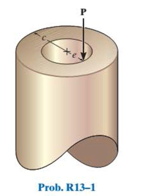
Find the maximum radius e at which the load P can be applied.
Answer to Problem 1RP
The maximum radius e at which the load P can be applied is
Explanation of Solution
Given information:
The post has a circular cross section of radius c.
Neglect the weight of the post.
Calculation:
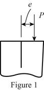
Sketch the Free Body Diagram of the applied load P as shown in Figure 1.
Apply the normal stress
Apply the stress formula as shown below.
Here, P is the applied load, A is the area of the cross section, M is the moment at the point, y is the centroid, and I is the moment of inertia.
Equate the Equation (1) and (2).
Determine the area of cross section as shown below.
Here, r is the radius of the cross section.
Substitute c for r .
Determine the moment of inertia as shown in below:
Substitute c for r .
Sketch the free body diagram of the moment at the point as shown in Figure 2.
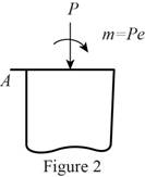
Refer to Figure 2.
Find the moment using the calculation.
Substitute
Therefore, the maximum radius e at which the load P can be applied is
Want to see more full solutions like this?
Chapter 13 Solutions
EBK STATICS AND MECHANICS OF MATERIALS
Additional Engineering Textbook Solutions
Vector Mechanics for Engineers: Statics and Dynamics
Elementary Surveying: An Introduction To Geomatics (15th Edition)
Experiencing MIS
Automotive Technology: Principles, Diagnosis, And Service (6th Edition) (halderman Automotive Series)
Fluid Mechanics: Fundamentals and Applications
Thermodynamics: An Engineering Approach


- Pearson eText Study Area mylabmastering.pearson.com Access Pearson P Pearson MyLab and Mastering Problem 15.106 P Course Home b Answered: HW_02.pdf EE 213-01 > Assignments HW_#... 8 of 8 Document Sharing User Settings The two spheres A and B each have a mass of 400 g. The spheres are fixed to the horizontal rods as shown in (Figure 1) and their initial velocity is 2 m/s. The mass of the supporting frame is negligible and it is free to rotate. Neglect the size of the spheres. Part A If a couple moment of M = 0.3 N · m is applied to the frame, determine the speed of the spheres in 3 s. Express your answer to three significant figures and include the appropriate units. Figure 1 of 1 ☐ ? v = Value Units Units input for part A Submit Request Answer Return to Assignment Provide Feedback ■Reviewarrow_forwardPearson eText Study Area Access Pearson mylabmastering.pearson.com P Pearson MyLab and Mastering Problem 15.79 P Course Home b Answered: HW_02.pdf EE 213-01 > Assignments HW_#... 6 of 8 > Document Sharing User Settings The two disks A and B have a mass of 4 kg and 5 kg, respectively. They collide with the initial velocities shown. The coefficient of restitution is e = 0.65. Suppose that (VA)1 = 6 m/s, (VB)1 = 8 m/s. (Figure 1) Part A Determine the magnitude of the velocity of A just after impact. Express your answer to three significant figures and include the appropriate units. Figure 1 of 1 μÅ (VA)2 = Value Units Submit Request Answer Part B ? Review Determine the angle between the x axis and the velocity of A just after impact, measured clockwise from the negative x axis. Express your answer in degrees to three significant figures. ΕΠΙ ΑΣΦ vec 01 Submit Request Answer Part C ? Determine the magnitude of the velocity of B just after impact. Express your answer to three significant…arrow_forward40.00 30.00 100.00- 100.00 P = 1000 N A=167 d=140.00 100.00- -b 20.00 200.00 Weld Strength P = 273 N/mm^2 Electrod E60 Safety factor S₁ = 3 Force P = 1000 N Using by SOLIDWORKSarrow_forward
- What are the reaction forces in A and B?arrow_forwardPearson eText Study Area Access Pearson mylabmastering.pearson.com P Pearson MyLab and Mastering Problem 15.6 P Course Home b Answered: HW_02.pdf EE 213-01 > Assignments HW_#... 3 of 8 ■ Review Document Sharing User Settings The jet plane has a mass of 250 Mg and a horizontal velocity of 100 m/s when t = 0. Part A If both engines provide a horizontal thrust which varies as shown in the graph in (Figure 1), determine the plane's velocity in 5 s. Neglect air resistance and the loss of fuel during the motion. Express your answer to three significant figures and include the appropriate units. Figure 1 of 1 > ☐ μÅ ? v = Value Units Submit Request Answer Provide Feedback Next >arrow_forwardAccess Pearson mylabmastering.pearson.com P Pearson MyLab and Mastering Problem 15.43 P Course Home b Answered: HW_02.pdf EE 213-01 > Assignments HW_#... Pearson eText Study Area Document Sharing User Settings The 20-g bullet is travelling at 400 m/s when it becomes embedded in the 2-kg stationary block. The coefficient of kinetic friction between the block and the plane is μk = 0.2. (Figure 1) Part A Determine the distance the block will slide before it stops. Express your answer to three significant figures and include the appropriate units. Figure 1 of 1 με S = Value Units Submit Request Answer Provide Feedback ? 4 of 8 Review Next >arrow_forward
- Access Pearson mylabmastering.pearson.com P Pearson MyLab and Mastering Problem 15.64 P Course Home b Answered: HW_02.pdf EE 213-01 > Assignments HW_#... 5 of 8 Pearson eText Study Area Document Sharing User Settings Ball A has a mass of 3 kg and is moving with a velocity of (VA)1 = 8 m/s when it makes a direct collision with ball B, which has a mass of 2.5 kg and is moving with a velocity of (VB) 1 = 4 m/s. Suppose that e = 0.7. Neglect the size of the balls. (Figure 1) Part A Determine the velocity of A just after the collision. ■Review Express your answer to three significant figures and include the appropriate units. Assume the positive direction is to the right. Figure 1 of 1 ◎ на ? (VA)2= Value Units Submit Request Answer Part B Determine the velocity of B just after the collision. Express your answer to three significant figures and include the appropriate units. Assume the positive direction is to the right. μÅ ? (VB)2= = Value Units Submit Request Answer Provide Feedback Next…arrow_forwardI only need help with number 3, actually just the theta dot portion. Thanks! I have Vr = 10.39 ft/sarrow_forwardOnly 100% sure experts solve it correct complete solutions okk don't use guidelines or ai answers okk will dislike okkk. Only human experts solved itarrow_forward
- Airplanes A and B, flying at constant velocity and at the same altitude, are tracking the eye of hurricane C. The relative velocity of C with respect to A is 300 kph 65.0° South of West, and the relative velocity of C with respect to B is 375 kph 50.0° South of East. A 120.0 km B 1N 1. Determine the relative velocity of B with respect to A. A ground-based radar indicates that hurricane C is moving at a speed of 40.0 kph due north. 2. Determine the velocity of airplane A. 3. Determine the velocity of airplane B. Consider that at the start of the tracking expedition, the distance between the planes is 120.0 km and their initial positions are horizontally collinear. 4. Given the velocities obtained in items 2 and 3, should the pilots of planes A and B be concerned whether the planes will collide at any given time? Prove using pertinent calculations. (Hint: x = x + vt) 0arrow_forwardOnly 100% sure experts solve it correct complete solutions okk don't use guidelines or ai answers okk will dislike okkk.arrow_forwardSolve this probem and show all of the workarrow_forward
 Elements Of ElectromagneticsMechanical EngineeringISBN:9780190698614Author:Sadiku, Matthew N. O.Publisher:Oxford University Press
 Mechanics of Materials (10th Edition)Mechanical EngineeringISBN:9780134319650Author:Russell C. HibbelerPublisher:PEARSON
 Thermodynamics: An Engineering ApproachMechanical EngineeringISBN:9781259822674Author:Yunus A. Cengel Dr., Michael A. BolesPublisher:McGraw-Hill Education
 Control Systems EngineeringMechanical EngineeringISBN:9781118170519Author:Norman S. NisePublisher:WILEY
 Mechanics of Materials (MindTap Course List)Mechanical EngineeringISBN:9781337093347Author:Barry J. Goodno, James M. GerePublisher:Cengage Learning
 Engineering Mechanics: StaticsMechanical EngineeringISBN:9781118807330Author:James L. Meriam, L. G. Kraige, J. N. BoltonPublisher:WILEY