Concept explainers
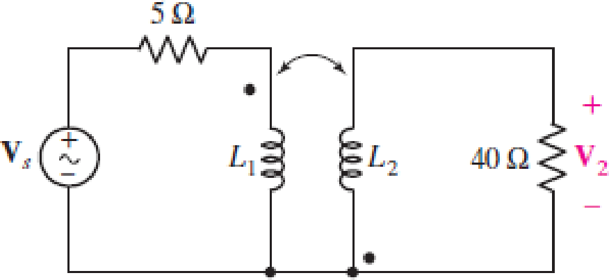
Obtain an expression for V2/Vs in the circuit of Fig. 13.68 if (a) L1 = 100 mH, L2 = 500 mH, and M is its maximum possible value; (b) L1 = 5L2 = 1.4 H and k = 87% of its maximum possible value; (c) the two coils can be treated as an ideal transformer, the left-hand coil having 500 turns and the right-hand coil having 10,000 turns.
FIGURE 13.68

(a)
Find the expression for
Answer to Problem 54E
The expression for
Explanation of Solution
Given data:
Refer to Figure 13.68 in the textbook for the given circuit.
The circuit parameters are given as follows:
Formula used:
Write the expression for reactance due to inductive coil of self-inductance as follows:
Here,
Write the expression for reactance due to inductive coil of mutual-inductance as follows:
Here,
Write the expression for mutual inductance as follows:
Here,
Calculation:
The maximum possible value of
Substitute 1 for
Observer the dot notation in the circuit, use the expression in Equations (1), (2), and apply KVL to the primary winding-loop in the given circuit as follows:
Simplify the expression as follows:
Substitute
Observer the dot notation, use the expression in Equations (1), (2), and apply KVL to the secondary winding-loop in the given circuit as follows:
Substitute
Substitute
From the given circuit, write the expression for
Rearrange the expression as follows:
Substitute
Rearrange the expression as follows:
Conclusion:
Thus, the expression for
(b)
Find the expression for
Answer to Problem 54E
The expression for
Explanation of Solution
Given data:
The circuit parameters are given as follows:
Calculation:
Find the value of
Substitute 0.87 for
Substitute 1.4 H for
Substitute 0.28 H for
Substitute
Substitute
Rearrange the expression as follows:
Conclusion:
Thus, the expression for
(c)
Find the expression for
Answer to Problem 54E
The expression for
Explanation of Solution
Given data:
The circuit parameters are given as follows:
Formula used:
Write the expression for transformer ratio as follows:
Here,
Write the expression for input impedance of the transformer as follows:
Here,
From the given circuit, write the expression for current through primary winding of the transformer as follows:
Calculation:
Substitute 500 for
Substitute 20 for
Substitute
From the given circuit, write the expression for
From Equation (12), substitute
Write the expression for transformer ratio in terms of voltages as follows:
Substitute 20 for
Rearrange the expression as follows:
Conclusion:
Thus, the expression for
Want to see more full solutions like this?
Chapter 13 Solutions
Loose Leaf for Engineering Circuit Analysis Format: Loose-leaf
- Q4: (A) Find the mean of a random variable X if S f(x)= 2x 0 2 for 0arrow_forward(A) Suopces the current measurements in a strip of wire are normally distributed with ca-10(mA) and a varieocom (mA)² 1- What is the probability that a current measurement lies between 7.4 and 11.6 mA? 2-Drew the probability density function of the current distribution. (8) A factory produces light bulbs with a koown probability of P(D)-0.08 that & bulo is dalective. If a bulb is defective, the probability that the quality control test detects it is defective is P(TID)-0.90. Conversely, if a bulb is not defective, the probability that the test Telesly indicaton k as defective is P(TID)-0.05. calculate the probability that a light b is notually defective given that the test result is positive, F(DIT).arrow_forwardTitle: Modelling and Simulating Boost Converter Battery Charging Powered by PV Solar Question: I need a MATLAB/Simulink model for a Boost Converter used to charge a battery, powered by a PV solar panel. The model should include: 1. A PV solar panel as the input power source. 2. A Boost Converter circuit for voltage regulation. 3. A battery charging system. 4. Simulation results showing voltage, current, and efficiency of the system. Please provide the Simulink file and any necessary explanations.arrow_forwardQ1. A 450 V, 50 Hz, 1450 r.p.m., 25 kW, star-connected three-phase induction motor delivers constant (rated) torque at all speeds. The motor equivalent circuit parameters at rated frequency are R1=0.12, R2 = 0.17 2, X₁ = 0.3 2, X2 = 0.5 2, Xm = 23.6 2. Smooth speed variation is obtained by primary frequency control with simultaneous variation of the terminal voltage to maintain constant air-gap flux. Calculate the motor current, power factor and efficiency at one-fifth of rated speed.arrow_forwardQ2. Drive the transformations for currents between a rotating balanced two phase (a,ẞ) winding and a pseudo stationary two phase (d,q) wingding.arrow_forwardThe formulas that should be used to solve the question are in the second picture, also B = k/n a= l/carrow_forwardarrow_back_iosSEE MORE QUESTIONSarrow_forward_ios
 Introductory Circuit Analysis (13th Edition)Electrical EngineeringISBN:9780133923605Author:Robert L. BoylestadPublisher:PEARSON
 Delmar's Standard Textbook Of ElectricityElectrical EngineeringISBN:9781337900348Author:Stephen L. HermanPublisher:Cengage Learning
 Programmable Logic ControllersElectrical EngineeringISBN:9780073373843Author:Frank D. PetruzellaPublisher:McGraw-Hill Education
 Fundamentals of Electric CircuitsElectrical EngineeringISBN:9780078028229Author:Charles K Alexander, Matthew SadikuPublisher:McGraw-Hill Education
 Electric Circuits. (11th Edition)Electrical EngineeringISBN:9780134746968Author:James W. Nilsson, Susan RiedelPublisher:PEARSON
 Engineering ElectromagneticsElectrical EngineeringISBN:9780078028151Author:Hayt, William H. (william Hart), Jr, BUCK, John A.Publisher:Mcgraw-hill Education,


