
Concept explainers
Calculate the impedance
Answer to Problem 25P
The impedance
Explanation of Solution
Given data:
Refer to Figure 13.94 in the textbook for the circuit with coupled coils.
The coupling co-efficient is 0.5.
Calculation:
Consider the expression for the mutual inductance.
Substitute 0.5 for k, 1 H for
From Figure 13.94, the value of
Consider the expression for the inductive reactance.
Substitute 1 H for L and
Substitute 2 H for L and
Consider the expression for the capacitive reactance.
Substitute 0.5 F for C and
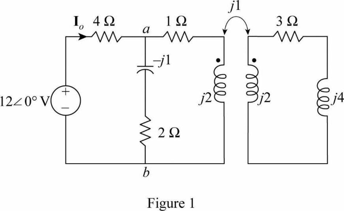
Modify the Figure 13.94 by transforming the time-domain circuit with coupled-coils to frequency domain of the circuit with coupled-coil. The frequency domain equivalent circuit is shown in Figure 1.
Write the expression for the impedance
Consider the expression for the reflected impedance
Substitute 2 for
Substitute
Simplify the Equation as follows.
Write the expression for the current
Substitute
The value of current
Convert the current from polar form to time domain form.
MATLAB code:
The MATLAB code using equations (3), (4) and (5) is,
M=0.5;
R2=3;
w=2;
L2=1;
ZL=4*j;
ZR=(w^2 * M^2)/(R2 + j*w*L2 + ZL);
Zab= (2-1*j)*(1+2*j+ZR)/(2-j+1+2*j+ZR)
Io=12/(Zab+4)
Then the MATLAB output is,
Zab = 1.4354 + 0.4639i
Io = 2.1918 - 0.1871i
Form the MATLAB output, impedance
Form the MATLAB output, current
The output is satisfied with analytical solution.
Conclusion:
Thus, the impedance
Want to see more full solutions like this?
Chapter 13 Solutions
EE 98: Fundamentals of Electrical Circuits - With Connect Access


- 12.3 Express each of the waveforms in Fig. P12.3 (on page 667) in terms of step functions and then determine its Laplace transform. [Recall that the ramp function is related to the step function by r(t − T) = (t − T) u(t − T).] Assume that all waveforms are zero for t<0. - - -arrow_forwardEvaluate each of the following integraarrow_forwardWith the aid of suitable diagrams, describe the benefits that antenna arrays have over singleelement antennas, with their applicationsarrow_forward
- Explain what is meant by an electric dipole antenna, sketch its radiation pattern, state itsdirectivity and describe its main applicationsarrow_forwardEstimate the length required for a half-waveelectric dipole antenna for transmitting/receiving EM waves at 800 MHz (this is in the UHFbandwidth of 470 to 860 MHz, used for UK TV transmissions).arrow_forwardIf the voltage waveform in Fig. 6.68 is applied to a 50-mH inductor, find the inductor current i(1). Assume i(0) = 0.arrow_forward
- Q3/A 8-pole, 3-phase, 50 Hz induction motor, running at 725 r.p.m, rotor is star connected its resistance and reactance 0.25 and 1.5 ohm per phase, the emf between slip rings is 100, find the rotor current per phase, power factor, synchronous speed, slip and rotor frequencyarrow_forward440 v, 4-pole, 3-phase, 50 Hz, star stator connected induction motor, full load speed 1425 r.p.m, rotor impedance 0.5+4.55ohm and rotor/stator ratio 0.8 calculate 1) starting torque, (2) rotor current (3) the value of external resistance to add to give maximum starting torque (4) power factor at maximum torque.arrow_forwardI would like to know the gear ratio and the tractive effort that a trolley must achieve with the following motor specifications: Voltage: 600 voltsSpeed: 1750 to 2300 RPMCurrent: 84 AmpsRated Power: 50-55 HP What percentage should be considered for gear efficiency, and what safe margin should be applied in these calculations? The constraints for the truck trolley are as follows:Maximum Speed: 50 MPHWeight of the Car Body: 46,000 lbs (the trolley weighs approximately 44,000 lbs)Diameter wheels: 86 inchesAdditionally, I would like to know how to plot a graph of tractive effort (in grams) versus speed (in MPH).arrow_forward
- A scientist proposed building an EM wave as E= 6000 sin (300 x -5000t) j + 6000 sin (300 x -5000t)k andB= -0.25 sin (300 x -5000t) i + 0.25 sin (300 x -5000t) k. Explain why this is not possible and explain all the mistakes E= 6000 sin (300 x -wt) j . Find the value for w and find the magnetic field vector and the Poynting vector as afunction of x and t.arrow_forwardSolve this problem and show all of the workarrow_forwardSolve this problem and show all of the workarrow_forward
 Introductory Circuit Analysis (13th Edition)Electrical EngineeringISBN:9780133923605Author:Robert L. BoylestadPublisher:PEARSON
 Delmar's Standard Textbook Of ElectricityElectrical EngineeringISBN:9781337900348Author:Stephen L. HermanPublisher:Cengage Learning
 Programmable Logic ControllersElectrical EngineeringISBN:9780073373843Author:Frank D. PetruzellaPublisher:McGraw-Hill Education
 Fundamentals of Electric CircuitsElectrical EngineeringISBN:9780078028229Author:Charles K Alexander, Matthew SadikuPublisher:McGraw-Hill Education
 Electric Circuits. (11th Edition)Electrical EngineeringISBN:9780134746968Author:James W. Nilsson, Susan RiedelPublisher:PEARSON
 Engineering ElectromagneticsElectrical EngineeringISBN:9780078028151Author:Hayt, William H. (william Hart), Jr, BUCK, John A.Publisher:Mcgraw-hill Education,