Principles of Foundation Engineering (MindTap Course List)
9th Edition
ISBN: 9781337705028
Author: Braja M. Das, Nagaratnam Sivakugan
Publisher: Cengage Learning
expand_more
expand_more
format_list_bulleted
Concept explainers
Textbook Question
Chapter 13, Problem 13.7P
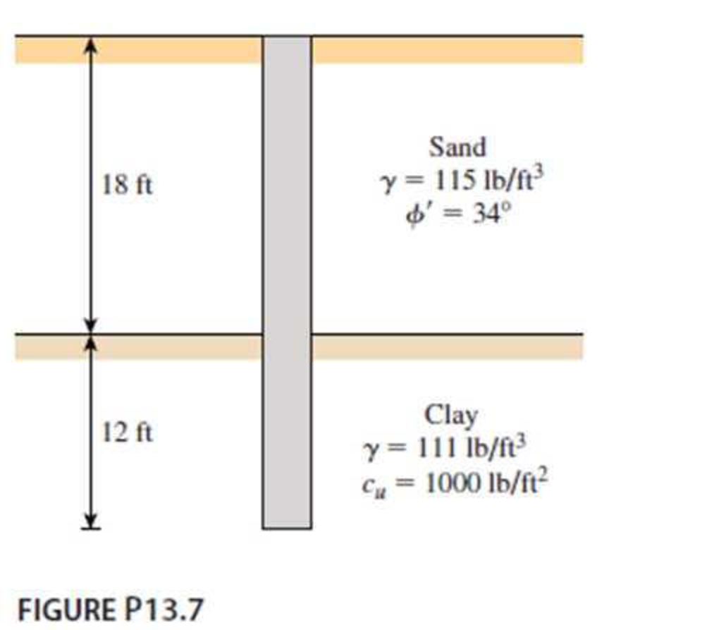
A 3 ft diameter straight drilled shaft is shown in Figure P13.7. Determine the load-carrying capacity of the drilled shaft with FS = 3. Take

Expert Solution & Answer
Trending nowThis is a popular solution!

Students have asked these similar questions
4.12 A 400 m vertical curve connects a -2.00% grade to a +4.00% grade. The P.I. is located
at station 150 + 00 and elevation 60.00 m above sea level. A pipe is to be located at
the low point on the vertical curve. The roadway at this point consists of two 3.6 m
lanes with a normal crown slope of 2%. If the lowest point on the surface of the road-
way must clear the pipe by 0.75 m, what is the station and maximum elevation of the
pipe?
=7.5 in., d1 = 1.5 in., b2 = 0.75 in., d2= 6.0 in., b3 = 3.0 in., and d3 = 2.0 in. Determine (a) the centroid location in inches from the
bottom surface. Round off to two decimal places.
M
H
b₂
y
...
d₁
M
by
dy
X
Vehicles arrive at a single park-entrance booth where a brochure is distributed. At 8 A.M., there are 20 vehicles in the queue and vehicles continue to arrive at the deterministic rate of λ(t) = 4.2 − 0.1t, where λ(t) is in vehicles per minute and t is in minutes after 8:00 A.M. From 8 A.M. until 8:10 A.M., vehicles are served at a constant deterministic rate of three per minute. Starting at 8:10 A.M., another brochure-distributing person is added and the brochure-service rate increases to six per minute (still
Chapter 13 Solutions
Principles of Foundation Engineering (MindTap Course List)
Ch. 13 - Prob. 13.1PCh. 13 - Prob. 13.2PCh. 13 - Prob. 13.3PCh. 13 - Determine the ultimate load-carrying capacity of...Ch. 13 - For the same data given in Problem 13.4, determine...Ch. 13 - Prob. 13.6PCh. 13 - A 3 ft diameter straight drilled shaft is shown in...Ch. 13 - Prob. 13.8PCh. 13 - Figure P13.9 shows a drilled shaft extending into...Ch. 13 - A free-headed drilled shaft is shown in Figure...
Knowledge Booster
Learn more about
Need a deep-dive on the concept behind this application? Look no further. Learn more about this topic, civil-engineering and related others by exploring similar questions and additional content below.Similar questions
- Vehicles arrive at a single park-entrance booth where a brochure is distributed. At 8 A.M., there are 20 vehicles in the queue and vehicles continue to arrive at the deterministic rate of λ(t) = 4.2 − 0.1t, where λ(t) is in vehicles per minute and t is in minutes after 8:00 A.M. From 8 A.M. until 8:10 A.M., vehicles are served at a constant deterministic rate of three per minute. Starting at 8:10 A.M., another brochure-distributing person is added and the brochure-service rate increases to six per minute (still at a single booth). Assuming D/D/1 queuing, determine the longest queue, the total delay from 8 A.M. until the queue dissipates; and the wait time of the 40th vehicle to arrive.arrow_forwardAt 8:00 A.M. there are 10 vehicles in a queue at a toll booth and vehicles are arriving at a rate of λ(t) = 6.9 − 0.2t. Beginning at 8 A.M., vehicles are being serviced at a rate of μ(t) = 2.1 + 0.3t [λ(t) and μ(t) are in vehicles per minute and t is in minutes after 8:00 A.M.]. Assuming D/D/1 queuing, what is the maximum queue length, and what would the total delay be from 8:00 A.M. until the queue clears?arrow_forwardIntroduction: Orifice and Free Flow Jet in Applied Fluid Mechanics' I need to introduction only for answerarrow_forward
- compute the load bearing capacity, displacement, stress distribution, tabulate the answersarrow_forwardcompute the load bearing capacity, displacement, and stress distribution, tabulate the answersarrow_forwardcompute the load bearing capacity, displacement, stress distribution, tabulate the answersarrow_forward
- By using the yield line theory, determine the ultimate resisting moment per linear meter (m) for an isotropic reinforced concrete two-way slab to sustain a concentrated factored load of P kN applied as shown in figure. Use equilibrium method in solution Column 2.0 P 8.0 m m m XXXXarrow_forwardBy using the yield line theory, determine the ultimate resisting moment (m) for an isotropic reinforced concrete two-way slab shown in figure under a uniform load (q). Use equilibrium method in solution m m column 20 m 20 marrow_forwardIn Tikrit city, environmental engineers are monitoring the diffusion of CO2 in the air as part of a pollution control study. The air-carbon dioxide mixture is at 295 K and 202.6 kPa, and the concentration of CO2 at two planes, 3 mm apart, is 25 vol.% at the first plane and 15 vol.% at the second plane. The diffusivity of CO2 in air under these conditions is 8.2 × 10⁶ m²/s. The study aims to calculate the rate of CO2 transfer across these two planes in two different scenarios: 1. What is the main engineering issue being addressed in this scenario? 2. Calculate the concentration of CO2 at the two planes in mol/m³ and determine the rate of transfer of CO2 using the diffusivity of CO2 in air. 3. With an engineering solution approach to solve the issue, calculate the rate of transfer of CO2 across the two planes assuming two scenarios: equimolecular counter diffusion and diffusion through a stagnant air layer. 4. Determine if there is a significant difference between the results of…arrow_forward
- Introduction: Orifice and Free Flow Jet in Applied Fluid Mechanics' I need to introduction only for answerarrow_forwardThe circular slab of radius 2 m supported by three columns, as shown in figure, is to be isotropically reinforced. Find the ultimate resisting moment per linear meter (m) required just to sustain a uniformly distributed load (q) equals 16 kN/m². Use equilibrium method in solution m Column marrow_forwardVehicles begin to arrive at a parking lot at 7:45 A.M. at a constant rate of 4 veh/min and continue to arrive at that rate throughout the day. The parking lot opens at 8:00 A.M. and vehicles are processed at a constant rate of one vehicle every 10 seconds. Assuming D/D/1 queuing, what is the longest queue, the queue at 8:15 A.M., and the average delay per vehicle from 7:45 A.M. until the queue clears?arrow_forward
arrow_back_ios
SEE MORE QUESTIONS
arrow_forward_ios
Recommended textbooks for you
 Principles of Foundation Engineering (MindTap Cou...Civil EngineeringISBN:9781337705028Author:Braja M. Das, Nagaratnam SivakuganPublisher:Cengage Learning
 Principles of Foundation Engineering (MindTap Cou...Civil EngineeringISBN:9781305081550Author:Braja M. DasPublisher:Cengage Learning
 Fundamentals of Geotechnical Engineering (MindTap...Civil EngineeringISBN:9781305635180Author:Braja M. Das, Nagaratnam SivakuganPublisher:Cengage Learning
 Principles of Geotechnical Engineering (MindTap C...Civil EngineeringISBN:9781305970939Author:Braja M. Das, Khaled SobhanPublisher:Cengage Learning

Principles of Foundation Engineering (MindTap Cou...
Civil Engineering
ISBN:9781337705028
Author:Braja M. Das, Nagaratnam Sivakugan
Publisher:Cengage Learning

Principles of Foundation Engineering (MindTap Cou...
Civil Engineering
ISBN:9781305081550
Author:Braja M. Das
Publisher:Cengage Learning

Fundamentals of Geotechnical Engineering (MindTap...
Civil Engineering
ISBN:9781305635180
Author:Braja M. Das, Nagaratnam Sivakugan
Publisher:Cengage Learning

Principles of Geotechnical Engineering (MindTap C...
Civil Engineering
ISBN:9781305970939
Author:Braja M. Das, Khaled Sobhan
Publisher:Cengage Learning
CE 414 Lecture 02: LRFD Load Combinations (2021.01.22); Author: Gregory Michaelson;https://www.youtube.com/watch?v=6npEyQ-2T5w;License: Standard Youtube License