Principles of Foundation Engineering (MindTap Course List)
9th Edition
ISBN: 9781337705028
Author: Braja M. Das, Nagaratnam Sivakugan
Publisher: Cengage Learning
expand_more
expand_more
format_list_bulleted
Concept explainers
Textbook Question
Chapter 13, Problem 13.4P
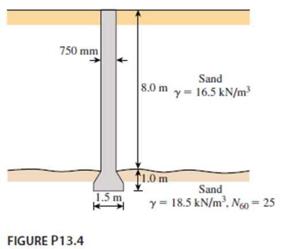
Determine the ultimate load-carrying capacity of the drilled shaft shown in Figure P13.4, using the Reese and O’Neill (1989) method.

Expert Solution & Answer
Trending nowThis is a popular solution!

Students have asked these similar questions
Q1) Determine the member end forces of the frames shown by utilizing structural symmetry and anti-symm.(Derive each
member forces and show BMD,SD,AFD)
20 kN/m
40 kN/m
C
D Hinge Ẹ
F
B
5 m
3 m
-3 m 5 m
E, I, A constant
12 m
Q1) Determine the member end forces of the frames shown by utilizing structural symmetry and anti-symm.(Derive each member forces and show BMD,SD,AFD)
Determine the symmetric and antisymmetric components of the loadings shown in the figure with respect to the axis of symmetry of the structure.
Chapter 13 Solutions
Principles of Foundation Engineering (MindTap Course List)
Ch. 13 - Prob. 13.1PCh. 13 - Prob. 13.2PCh. 13 - Prob. 13.3PCh. 13 - Determine the ultimate load-carrying capacity of...Ch. 13 - For the same data given in Problem 13.4, determine...Ch. 13 - Prob. 13.6PCh. 13 - A 3 ft diameter straight drilled shaft is shown in...Ch. 13 - Prob. 13.8PCh. 13 - Figure P13.9 shows a drilled shaft extending into...Ch. 13 - A free-headed drilled shaft is shown in Figure...
Knowledge Booster
Learn more about
Need a deep-dive on the concept behind this application? Look no further. Learn more about this topic, civil-engineering and related others by exploring similar questions and additional content below.Similar questions
- What are some software tools that have been designed to produce an automatic quantity takeoff in construction?arrow_forwardWhen constructing a sand volleyball court how would you control drainage and erosion, mitigation dust and noise, and control traffic on the construction site?arrow_forwardWhat are the building code requirements when building an outdoor sand volleyball court in Kentucky?arrow_forward
- H.W. A soil profile is shown in figure below. Calculate the values of ot, o', u at points A, B, C and D. draw the variation of ot, o', u with the depth. 3m Water table 2.5m + 2m D Rock Dry sand, e=0.52, Gs=2.65 Sand, e=0.52, Gs=2.65 Clay, w=45%, e = 1.22arrow_forwardNo chatgpt pls will upvotearrow_forwardCalculate steel quantity in kg for CF3, CF4,CF5, CF6 from foundation layout and other footing? The depth of CF3, CF4,CF5 and CF6 are 50, 55,55 , 60 cm in order. Both long and short bar for CF3, CF4,CF5 and CF6 are Y14@15c/c T&B, Y14@15c/c T&B, Y14@15c/c T&B, Y14@12c/c T&B in order. 2. Calculate quantity of flexible sheet from foundation layout?arrow_forward
- (A): As shown in the rig. A hydraulic jump was occurred in a rectangular channel,the velocity of flow before and after the jump equal to 8 m/s and 2 m/s respectively. Find: The energy dissipation for the jump (AE) and what is the name of this jump. V1-8 m/s -V2-2 m/sarrow_forwardA cylinder of fluid has dimensions of 0.2 ft in diameter by 0.45 ft high. If the weight of thefluid is 0.55 lb , determine the specific gravity and density of fluid.arrow_forwardA cylinder of fluid has dimensions of 0.2 ft in diameter by 0.45 ft high. If the weight of thefluid is 0.55 lb , determine the specific gravity and density of fluid.arrow_forward
- A cylinder of fluid has dimensions of 0.2 ft in diameter by 0.45 ft high. If the weight of thefluid is 0.55 lb , determine the specific gravity and density of fluid.arrow_forwardDraw the shear and bending moment diagrams and find the immediate deflection for a simply supported beam of length 20 ft. with the same live load at ½ span and cross-section as the previous problem. Assume a reasonable Modulus of Elasticity and concrete self-weight. Hint: You may look online for typical concrete self-weights and compressive strengths. You may also use the ACI 318 Code equation for the Modulus of Elasticity shown below, and the supplied Design Aids.arrow_forwardProblem 4. A major transmission pathway of the novel coronavirus disease 2019 (COVID- 19) is through droplets and aerosols produced by violent respiratory events such as sneezes and coughs (Fig. 1). For the purpose of providing public health guidelines, we would like to estimate the amount of time it takes for these droplets to settle from air to the ground. The relevant parameters are the settling time (ts), the initial height of the droplets (H), gravitational acceleration (g), density of the droplets (pa), radius of the droplets (R), as well as dynamic viscosity of the ambient air (Pair). Use dimensional analysis and the Buckingham theorem to answer the following questions: 1. Find the independent dimensionless parameters using the table method. Then, express the settling time as a function of the other relevant parameters. Your solution should match the physical intuition that the settling time scales linearly with the initial height. 2. How would the settling change if the…arrow_forward
arrow_back_ios
SEE MORE QUESTIONS
arrow_forward_ios
Recommended textbooks for you
 Principles of Foundation Engineering (MindTap Cou...Civil EngineeringISBN:9781337705028Author:Braja M. Das, Nagaratnam SivakuganPublisher:Cengage Learning
 Principles of Foundation Engineering (MindTap Cou...Civil EngineeringISBN:9781305081550Author:Braja M. DasPublisher:Cengage Learning
 Fundamentals of Geotechnical Engineering (MindTap...Civil EngineeringISBN:9781305635180Author:Braja M. Das, Nagaratnam SivakuganPublisher:Cengage Learning
 Principles of Geotechnical Engineering (MindTap C...Civil EngineeringISBN:9781305970939Author:Braja M. Das, Khaled SobhanPublisher:Cengage Learning

Principles of Foundation Engineering (MindTap Cou...
Civil Engineering
ISBN:9781337705028
Author:Braja M. Das, Nagaratnam Sivakugan
Publisher:Cengage Learning

Principles of Foundation Engineering (MindTap Cou...
Civil Engineering
ISBN:9781305081550
Author:Braja M. Das
Publisher:Cengage Learning

Fundamentals of Geotechnical Engineering (MindTap...
Civil Engineering
ISBN:9781305635180
Author:Braja M. Das, Nagaratnam Sivakugan
Publisher:Cengage Learning

Principles of Geotechnical Engineering (MindTap C...
Civil Engineering
ISBN:9781305970939
Author:Braja M. Das, Khaled Sobhan
Publisher:Cengage Learning
Types of Foundation in building construction in detail - Civil Engineering Videos; Author: Civil Engineers;https://www.youtube.com/watch?v=7sl4KuM4UIE;License: Standard YouTube License, CC-BY
Types of Foundation || Foundation Engineering; Author: Civil Engineering;https://www.youtube.com/watch?v=AFLuAKGhanw;License: Standard Youtube License