
(a)
Find the factor of safety with respect to sliding for case (a).
(a)
Answer to Problem 13.22P
The factor of safety with respect to sliding for case (a) is
Explanation of Solution
Given information:
The bed slope
The angle
The cohesion
The unit weight of the soil
The depth (H) of slope is 15.2 m.
Calculation:
Calculate slope angle
Substitute 2 for
Assume the developed angle of friction
Find the factor of safety
Substitute
Find the Taylor’s stability number (m).
Refer Figure 13.17, “Taylor’s stability number” in the textbook.
Take the value of Taylor’s stability number corresponding friction angle
The Taylor’s stability number (m) is 0.098.
Find the developed cohesion
Substitute
Find the factor of safety with respect to cohesion
Substitute
Similarly find the factor of safety
Summarize the values of the factor of safety
| m | ||||
| 5 | 2.01 | 0.098 | 25.76 | 1.30 |
| 6 | 1.68 | 0.090 | 23.65 | 1.41 |
| 8 | 1.25 | 0.078 | 20.50 | 1.63 |
| 10 | 1 | 0.064 | 16.82 | 1.99 |
Plot the graph of factor of safety
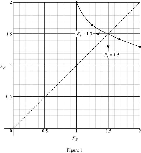
Refer Figure 1.
Find the factor of safety
Draw a line from origin of the graph with an angle of
Therefore, the factor of safety with respect to sliding for case (a) is
(b)
Find the factor of safety with respect to sliding for case (b).
(b)
Answer to Problem 13.22P
The factor of safety with respect to sliding for case (b) is
Explanation of Solution
Given information:
The bed slope
The angle
The cohesion
The unit weight of the soil
The depth (H) of slope is 9.15 m.
Calculation:
Calculate slope angle
Substitute 1 for
Assume the developed angle of friction
Find the factor of safety
Substitute
Find the Taylor’s stability number (m).
Refer Figure 13.17, “Taylor’s stability number” in the textbook.
Take the value of Taylor’s stability number corresponding friction angle
The Taylor’s stability number is 0.133.
Find the developed cohesion
Substitute
Find the factor of safety with respect to cohesion
Substitute
Similarly find the factor of safety
Summarize the values of the factor of safety
| m | ||||
| 5 | 4.16 | 0.133 | 22 | 0.87 |
| 10 | 2.06 | 0.105 | 17.37 | 1.10 |
| 15 | 1.36 | 0.080 | 13.23 | 1.45 |
| 20 | 1 | 0.058 | 9.7 | 2 |
Plot the graph of factor of safety
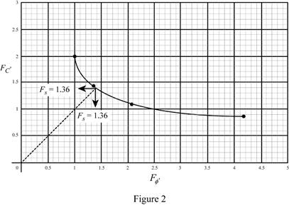
Refer Figure 2.
Find the factor of safety
Draw a line from origin of the graph with an angle of
Therefore, the factor of safety with respect to sliding for case (b) is
Want to see more full solutions like this?
Chapter 13 Solutions
Fundamentals of Geotechnical Engineering (MindTap Course List)

- A shallow foundation measuring 1 m × 2 m in plan is to be constructed over a normally consolidated sand layer. Given: D₁ = 1 m, №60 increases with depth, N 60 (in the depth of stress influence) = 11, Estimate the elastic settlement using Burland and Burbidge's method. (Enter your answer to three significant figures.) Se mm and Inet = 138 kN/m².arrow_forwardA continuous foundation on a deposit of sand layer is shown in the figure below along with the variation of the cone penetration resistance qc 1.5 m 0 2.5 m Sand 14 q= 195 kN/m² qe (kN/m²) 9 1750 93450 9c=2900 Depth (m) Assuming = 16 kN/m² and creep is at the end of ten years after construction, calculate the elastic settlement of the foundation using the strain influence factor method. Use the equations 22 Iz Es 0 | Se = C₁C2 (9) Az and Es = 3.5qc (for L/B> 10) (Enter your answer to three significant figures.) Se = mmarrow_forwardDetermine the stiffness matrices for the entire truss in the global co-ordinate system. Assume A=0.0015m2 and E=200GPa, indicate the degrees of freedom in all stiffness matricies.arrow_forward
- need helparrow_forwardNEED HELP.arrow_forwardnent 6-Transverse Shear & Deflection ↓ 2 of 2 -+ Automatic Zoom 4.) The built-up wooden beam shown is subjected to a vertical shear of 8 kN. Knowing the the nails are spaced longitudinally every 60 mm at A and every 25 mm at B, determine the shear force in the nails at A and B. (5 points) 50 300- 400 A 50 A C 150 B A 100 50 200 A B Dimensions in mm 5.) A 2.5 inch x 5.5 inch rectangular Southern pine section (E=1.8 x 10³ ksi) is used in an 8 ft cantilever span subjected to the loads shown. Compute the deflections at point A. (4 points) Дarrow_forward
- E:/school%20pack/BENG%202/EG231/STATICS/LECTURE%20NOTES/PRACTICE%20QUESTIONS/EG%20231%20Chap-5%20Practice%20Que PDF 豆豆豆豆豆豆 aw V Aa | Ask Copilot - + 4 of 8 D 3. Calculate the y-coordinate of the centroid of the shaded area. 74 mm y 3232 mm mm DELL 32 mm -x F1 F2 F3 F4 F5 F6 F7 F8 F9 prt sc F10 home end F11 F 2 W E3 $ 4 € 95 % & 6 7 8 * 00 R T Y כ 9 O Parrow_forward*8-60. The 2-in.-diameter rod is subjected to the forces shown. Determine the state of stress at point B, and show the results on a differential element located at this point. Probs. 8-59/60 B 8 in. 600 lb 12 in. 500 lb 800 lbarrow_forwardfind SFD and BMD by using slope deflection methodarrow_forward
- The following relates to Problems 4 and 5. Christchurch, New Zealand experienced a major earthquake on February 22, 2011. It destroyed 100,000 homes. Data were collected on a sample of 300 damaged homes. These data are saved in the file called CIEG315 Homework 4 data.xlsx, which is available on Canvas under Files. A subset of the data is shown in the accompanying table. Two of the variables are qualitative in nature: Wall construction and roof construction. Two of the variables are quantitative: (1) Peak ground acceleration (PGA), a measure of the intensity of ground shaking that the home experienced in the earthquake (in units of acceleration of gravity, g); (2) Damage, which indicates the amount of damage experienced in the earthquake in New Zealand dollars; and (3) Building value, the pre-earthquake value of the home in New Zealand dollars. PGA (g) Damage (NZ$) Building Value (NZ$) Wall Construction Roof Construction Property ID 1 0.645 2 0.101 141,416 2,826 253,000 B 305,000 B T 3…arrow_forwardfind SFD and BMDarrow_forwardThe data needed to answer this question is given by this link: https://docs.google.com/spreadsheets/d/1vzb03U7Uvzm7X-by3OchQNwYeREzbP6Z-xzZMP2tzNw/edit?usp=sharing if it is easier to make a copy of the data because it is on view only then feel free to do so.arrow_forward
 Principles of Geotechnical Engineering (MindTap C...Civil EngineeringISBN:9781305970939Author:Braja M. Das, Khaled SobhanPublisher:Cengage Learning
 Fundamentals of Geotechnical Engineering (MindTap...Civil EngineeringISBN:9781305635180Author:Braja M. Das, Nagaratnam SivakuganPublisher:Cengage Learning
 Principles of Foundation Engineering (MindTap Cou...Civil EngineeringISBN:9781305081550Author:Braja M. DasPublisher:Cengage Learning
 Principles of Foundation Engineering (MindTap Cou...Civil EngineeringISBN:9781337705028Author:Braja M. Das, Nagaratnam SivakuganPublisher:Cengage Learning