
Concept explainers
Videos
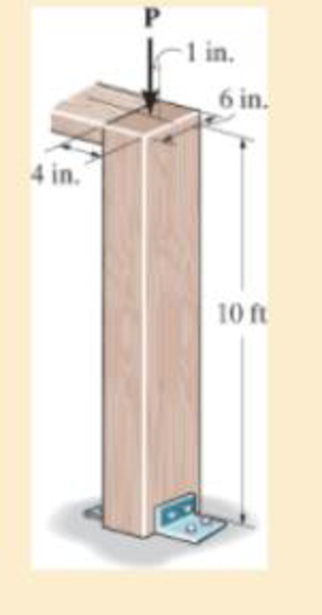
The wood column has a thickness of 4 in. and a width of 6 in. Using the NFPA equations of Sec.13.6 and Eq.13-30, determine the maximum allowable eccentric load P that can be applied. Assume that the column is pinned at both its top and bottom.
R13−1
Answer to Problem 13.1RP
The maximum allowable eccentric load on the column is
Explanation of Solution
Given information:
The load applied on the wooden column is
The column is pinned at both the ends.
The width of cross-sectional area of the column is
The depth of cross-sectional area of the column is
The length of the column is
Show the expression ofNFPA Equation of Sec 13.6 as follows:
Here,
Show the expression for Equation 13-30 as follows:
Here,
Calculation:
Calculate the cross-sectional area
Substitute
Calculate the moment of inertia using the relation:
Substitute
The ends of the column are pinned. Thus, the value of
Calculate the value of
Substitute
The value of
Show the expression of NFPA Equation of Sec 13.6 as follows:
Here,
Substitute 30 for
Show the expression for Equation 13-30 as follows:
Here,
The eccentricity
Calculate the value of c using the relation:
Substitute
Substitute
Thus, the maximum allowable eccentric load on the column is
Want to see more full solutions like this?
Chapter 13 Solutions
Mechanics of Materials (10th Edition)
Additional Engineering Textbook Solutions
Modern Database Management
Fluid Mechanics: Fundamentals and Applications
Elementary Surveying: An Introduction To Geomatics (15th Edition)
Java: An Introduction to Problem Solving and Programming (8th Edition)
Automotive Technology: Principles, Diagnosis, And Service (6th Edition) (halderman Automotive Series)
Vector Mechanics for Engineers: Statics and Dynamics


- Question 22: The superheated steam powers a steam turbine for the production of electrical power. The steam expands in the turbine and at an intermediate expansion pressure (0.1 MPa) a fraction is extracted for a regeneration process in a surface regenerator. The turbine has an efficiency of 90%. It is requested: Define the Power Plant Schematic Analyze the steam power system considering the steam generator system in the attached figure Determine the electrical power generated and the thermal efficiency of the plant Perform an analysis on the power generated and thermal efficiency considering a variation in the steam fractions removed for regeneration ##Data: The steam generator uses biomass from coconut shells to produce 4.5 tons/h of superheated steam; The feedwater returns to the condenser at a temperature of 45°C (point A); Monitoring of the operating conditions in the steam generator indicates that the products of combustion leave the system (point B) at a temperature of 500°C;…arrow_forwardThis is an old practice exam question.arrow_forwardSteam enters the high-pressure turbine of a steam power plant that operates on the ideal reheat Rankine cycle at 700 psia and 900°F and leaves as saturated vapor. Steam is then reheated to 800°F before it expands to a pressure of 1 psia. Heat is transferred to the steam in the boiler at a rate of 6 × 10⁴ Btu/s. Steam is cooled in the condenser by the cooling water from a nearby river, which enters the condenser at 45°F. Use steam tables. NOTE: This is a multi-part question. Once an answer is submitted, you will be unable to return to this part. Determine the pressure at which reheating takes place. Use steam tables. Find: The reheat pressure is psia. (P4)Find thermal efficiencyFind m dotarrow_forward
- Air at T1 = 24°C, p1 = 1 bar, 50% relative humidity enters an insulated chamber operating at steady state with a mass flow rate of 3 kg/min and mixes with a saturated moist air stream entering at T2 = 7°C, p2 = 1 bar. A single mixed stream exits at T3 = 17°C, p3 = 1 bar. Neglect kinetic and potential energy effects Determine mass flow rate of the moist air entering at state 2, in kg/min Determine the relative humidity of the exiting stream. Determine the rate of entropy production, in kJ/min.Karrow_forwardAir at T1 = 24°C, p1 = 1 bar, 50% relative humidity enters an insulated chamber operating at steady state with a mass flow rate of 3 kg/min and mixes with a saturated moist air stream entering at T2 = 7°C, p2 = 1 bar. A single mixed stream exits at T3 = 17°C, p3 = 1 bar. Neglect kinetic and potential energy effects Determine mass flow rate of the moist air entering at state 2, in kg/min Determine the relative humidity of the exiting stream. Determine the rate of entropy production, in kJ/min.Karrow_forwardAir at T1 = 24°C, p1 = 1 bar, 50% relative humidity enters an insulated chamber operating at steady state with a mass flow rate of 3 kg/min and mixes with a saturated moist air stream entering at T2 = 7°C, p2 = 1 bar. A single mixed stream exits at T3 = 17°C, p3 = 1 bar. Neglect kinetic and potential energy effects (a) Determine mass flow rate of the moist air entering at state 2, in kg/min (b) Determine the relative humidity of the exiting stream. (c) Determine the rate of entropy production, in kJ/min.Karrow_forward
- A simple ideal Brayton cycle operates with air with minimum and maximum temperatures of 27°C and 727°C. It is designed so that the maximum cycle pressure is 2000 kPa and the minimum cycle pressure is 100 kPa. The isentropic efficiencies of the turbine and compressor are 91% and 80%, respectively, and there is a 50 kPa pressure drop across the combustion chamber. Determine the net work produced per unit mass of air each time this cycle is executed and the cycle’s thermal efficiency. Use constant specific heats at room temperature. The properties of air at room temperature are cp = 1.005 kJ/kg·K and k = 1.4. The fluid flow through the cycle is in a clockwise direction from point 1 to 4. Heat Q sub in is given to a component between points 2 and 3 of the cycle. Heat Q sub out is given out by a component between points 1 and 4. An arrow from the turbine labeled as W sub net points to the right. The net work produced per unit mass of air is kJ/kg. The thermal efficiency is %.arrow_forwardSteam enters the high-pressure turbine of a steam power plant that operates on the ideal reheat Rankine cycle at 700 psia and 900°F and leaves as saturated vapor. Steam is then reheated to 800°F before it expands to a pressure of 1 psia. Heat is transferred to the steam in the boiler at a rate of 6 × 10⁴ Btu/s. Steam is cooled in the condenser by the cooling water from a nearby river, which enters the condenser at 45°F. Use steam tables. NOTE: This is a multi-part question. Once an answer is submitted, you will be unable to return to this part. Determine the pressure at which reheating takes place. Use steam tables. The reheat pressure is psia.Find thermal efficieny Find m dotarrow_forwardThis is an old exam practice question.arrow_forward
- As shown in the figure below, moist air at T₁ = 36°C, 1 bar, and 35% relative humidity enters a heat exchanger operating at steady state with a volumetric flow rate of 10 m³/min and is cooled at constant pressure to 22°C. Ignoring kinetic and potential energy effects, determine: (a) the dew point temperature at the inlet, in °C. (b) the mass flow rate of moist air at the exit, in kg/min. (c) the relative humidity at the exit. (d) the rate of heat transfer from the moist air stream, in kW. (AV)1, T1 P₁ = 1 bar 11 = 35% 120 T₂=22°C P2 = 1 bararrow_forwardAir at T₁-24°C, p₁-1 bar, 50% relative humidity enters an insulated chamber operating at steady state with a mass flow rate of 3 kg/min and mixes with a saturated moist air stream entering at T₂-7°C, p2-1 bar. A single mixed stream exits at T3-17°C, p3-1 bar. Neglect kinetic and potential energy effects Step 1 Your answer is correct. Determine mass flow rate of the moist air entering at state 2, in kg/min. m2 = 2.1 Hint kg/min Using multiple attempts will impact your score. 5% score reduction after attempt 2 Step 2 Determine the relative humidity of the exiting stream. Փ3 = i % Attempts: 1 of 3 usedarrow_forwardA reservoir at 300 ft elevation has a 6-in.-diameter discharge pipe located 50 ft below the surface. The pipe is 600 ft long and drops in elevation to 150 ft where the flow discharges to the atmosphere. The pipe is made of riveted steel with a roughness height of 0.005 ft. Determine the flow rate without a head loss Determine the flow rate with the pipe friction head loss. (hints: Since the velocity is not known for part b and the Reynolds number and friction factor depend on velocity, you will need to iterate to find the solution. A good first guess is the velocity from part (a))arrow_forward
 Mechanics of Materials (MindTap Course List)Mechanical EngineeringISBN:9781337093347Author:Barry J. Goodno, James M. GerePublisher:Cengage Learning