
Concept explainers
Videos
through 13.6 Calculate the reactions at points A and BFor the beams shown.
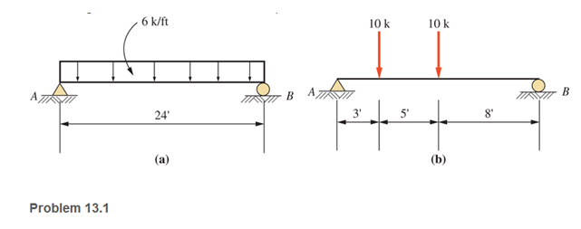
a.
The reaction forces at points A and B
Answer to Problem 13.1P
Explanation of Solution
Given:
The beam diagram and loading are given as shown below:
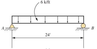
Concept Used:
Replacing the uniformly distribute load by a concentrated external load
Calculation:
Taking anticlockwise moment positive, the summation of all moment of forces at point A equals to zero
For vertical equilibrium, the summation of forces in vertical direction must be zero
Conclusion:
Therefore, the reaction force at points A,
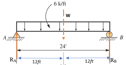
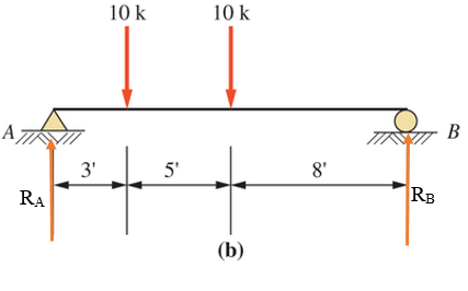
b.
The reaction forces at points A and B
Answer to Problem 13.1P
Explanation of Solution
Given:
The beam diagram and loading are given as shown below
Concept Used:
The reaction forces at point A and B are shown below in the figure and assumed to act in the upward (positive) direction
Calculation:
Taking anticlockwise moment positive, the summation of all moment of forces at point A equals to zero
For vertical equilibrium, the summation of forces in vertical direction must be zero
Conclusion:
Therefore, the forces are
Want to see more full solutions like this?
Chapter 13 Solutions
Applied Statics and Strength of Materials (6th Edition)
Additional Engineering Textbook Solutions
Web Development and Design Foundations with HTML5 (8th Edition)
Modern Database Management
Mechanics of Materials (10th Edition)
Starting Out with Java: From Control Structures through Data Structures (4th Edition) (What's New in Computer Science)
Starting Out with C++ from Control Structures to Objects (9th Edition)
Thinking Like an Engineer: An Active Learning Approach (4th Edition)


- Q6: A turbocharged engine with a compression ratio of 8 is being designed using an air standard cycle. The ambient air is assumed to be 300K and 100 kPa. The temperature at the end of the compression in the cylinder is desired to be 1000K, assuming no combustion prior to reaching TDC. At the end of the cylinder expansion the temperature is also desired to be 1000K. If both the turbine and the compressor have mechanical efficiencies of 80%, what will be the pressure ratio of the compressor and what will be the turbine exhaust temperature?arrow_forwardQ5: A 5.6 litre V8 engine with a compression ratio of 9.4:1 operates on an air-standard Otto cycle at 2800 RPM, with a volumetric efficiency of 90 % and a stoichiometric air-fuel ratio using gasoline. The exhaust flow undergoes a temperature drop of 44ºC as it passes through the turbine of the supercharger. Calculate (a) mass flow rate of exhaust gas and (b) power available to drive the turbocharger compressor.arrow_forwarddo handwrittenarrow_forward
- Create a report: An example of two people who do not understand each other due to lack of communication, and mention ways to resolve the issue between them .arrow_forwardI want the kinematic diagram to be draw like this plsarrow_forwardAccording to the principles and steps above, draw the kinematic diagram of following mechanisms. Mark the appropriate scale, calculates the degree of freedom. NO.1 NO.2 NO: 3 NO.: 4arrow_forward
- An office building is planned with a lateral-force-resisting system designed for earthquake resistance in aseismic zone. The seismic capacity of the proposed system, expressed as a force factor, is assumed tofollow a lognormal distribution with a median of 6.5 and a standard deviation of 1.5. The ground motionfrom the largest expected earthquake at the site is estimated to correspond to an equivalent force factor of 5.5.(a) What is the estimated probability that the building will experience damage when subjected to the largest expected earthquake? (b) If the building survives (i.e., experiences no damage) during a previous moderate earthquake with aforce factor of 4.0, what is the updated probability of failure of the building under the largest expectedearthquake?(c) Suppose future occurrences of the largest expected earthquake follow a Poisson process with a mean return period of 500 years. Assuming that damage events from different earthquakes are statisticallyindependent,…arrow_forwardDuring a plant visit, it was noticed that a 12-m-long section of a 10-cm-diameter steam pipe is completely exposed to the ambient air. The temperature measurements indicate that the average temperature of the outer surface of the steam pipe is 75°C when the ambient temperature is 5°C. There are also light winds in the area at 10 km/h. The emissivity of the outer surface of the pipe is 0.8, and the average temperature of the surfaces surrounding the pipe, including the sky, is estimated to be 0°C. Determine the amount of heat lost from the steam during a 10-h-long work day. Steam is supplied by a gas-fired steam generator that has an efficiency of 80 percent, and the plant pays $1.05/therm of natural gas. If the pipe is insulated and 90 percent of the heat loss is saved, determine the amount of money this facility will save a year as a result of insulating the steam pipes. Assume the plant operates every day of the year for 10 h. State your assumptions.arrow_forwardAn old fashioned ice cream kit consists of two concentric cylinders of radii Ra and Rb. The inner cylinder is filled with milk and ice cream ingredients while the space between the two cylinders is filled with an ice-brine mixture. Ice cream begins to form on the inner surface of the inner cylinder. To expedite the process, would you recommend rotating the inner cylinder? Justify your recommendation. icecream/ ice-brine Ra Rbarrow_forward
- Find temperatures STRICTLY USING RITZ APPROXIMATION METHODarrow_forwardSolve this Problem using RITZ APPROXIMATION. STEP BY STEParrow_forwardB/40 The body is constructed of a uniform square plate, a uniform straight rod, a uniform quarter‐circular rod, and a particle (negligible dimensions). If each part has the indicated mass, determine the mass moments of inertia of the body about the x‐, y‐, and z‐axes. Answer Given.arrow_forward
 Elements Of ElectromagneticsMechanical EngineeringISBN:9780190698614Author:Sadiku, Matthew N. O.Publisher:Oxford University Press
 Mechanics of Materials (10th Edition)Mechanical EngineeringISBN:9780134319650Author:Russell C. HibbelerPublisher:PEARSON
 Thermodynamics: An Engineering ApproachMechanical EngineeringISBN:9781259822674Author:Yunus A. Cengel Dr., Michael A. BolesPublisher:McGraw-Hill Education
 Control Systems EngineeringMechanical EngineeringISBN:9781118170519Author:Norman S. NisePublisher:WILEY
 Mechanics of Materials (MindTap Course List)Mechanical EngineeringISBN:9781337093347Author:Barry J. Goodno, James M. GerePublisher:Cengage Learning
 Engineering Mechanics: StaticsMechanical EngineeringISBN:9781118807330Author:James L. Meriam, L. G. Kraige, J. N. BoltonPublisher:WILEY