
Introductory Circuit Analysis; Laboratory Manual For Introductory Circuit Analysis Format: Kit/package/shrinkwrap
13th Edition
ISBN: 9780134297446
Author: Boylestad, Robert L.
Publisher: Prentice Hall
expand_more
expand_more
format_list_bulleted
Concept explainers
Videos
Textbook Question
Chapter 13, Problem 10P
For the oscilloscope pattern of Fig. 13.89:
a. Determine the peak amplitude.
b. Find the period.
c. Calculate the frequency.
Redraw the oscilloscope pattern if a
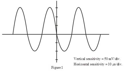
Vertical sensitivity =
Horizontal sensitivity = 10
Expert Solution & Answer
Want to see the full answer?
Check out a sample textbook solution
Students have asked these similar questions
NEED HANDWRITTEN SOLUTION PLEASE DO NOT USE AI
Not: I need also pictures
cct diagram and result
Question:
I need a MATLAB/Simulink model for a
Boost Converter used to charge a battery,
powered by a PV solar panel. The model
should include:
1. A PV solar panel as the input power
source.
2. A Boost Converter circuit for voltage
regulation.
3. A battery charging system.
4. Simulation results showing voltage,
current, and efficiency of the system.
Determine the node voltages V1, V2, V3, and V4, for the circuit shown in the figure
where R1-15.2, R2=652, R3-72 and R4=5.2.
5 V
V2
R1
w
V1
R2
V3
R3
+
1.25 A
R4
①1.25
V4
15 V
Chapter 13 Solutions
Introductory Circuit Analysis; Laboratory Manual For Introductory Circuit Analysis Format: Kit/package/shrinkwrap
Ch. 13 - For the sinusoidal waveform in Fig. 13.85: a. What...Ch. 13 - For the sinusoidal signal in Fig. 13.86: a. What...Ch. 13 - For the periodic square-wave waveform in Fig....Ch. 13 - For the waveform of Fig. 13.88: a. Does this...Ch. 13 - Find the period of a periodic waveform whose...Ch. 13 - Find the frequency of a repeating waveform whose...Ch. 13 - If a periodic waveform has a frequency of 1 kHz,...Ch. 13 - Find the period of a sinusoidal waveform that...Ch. 13 - What is the frequency of periodic waveform that...Ch. 13 - For the oscilloscope pattern of Fig. 13.89: a....
Ch. 13 - For the waveform of Fig. 13.90: a. What is the...Ch. 13 - Convert the following degrees to radians: a. 40 b....Ch. 13 - Convert the following radians to degrees: /3 1.2...Ch. 13 - Find the angular velocity of a waveform with a...Ch. 13 - Find the angular velocity of a waveform with a...Ch. 13 - Find the frequency and period of sine waves having...Ch. 13 - Given f=60Hz, determine how long it will take the...Ch. 13 - If a sinusoidal waveform passes through an angle...Ch. 13 - Find the amplitude and frequency of the following...Ch. 13 - Sketch 6 sin 754t with the abscissa angle in...Ch. 13 - Sketch 8sin280t with the abscissa angle in...Ch. 13 - If e=300sin157t, how long (in second) does it take...Ch. 13 - Giveni=0.5sindetermine=72.Ch. 13 - Givenv=20determine=1.2.Ch. 13 - Givenv=30103determinetheanglesatwhichuwillbe6mV.Ch. 13 - If v=40Vat=30andt=1ms, determine the mathematical...Ch. 13 - Sketch sin (377t+60) with the abscissa angle in...Ch. 13 - Sketch the following waveforms: 50sin(wt+0)...Ch. 13 - Write the analytical expression for the waveforms...Ch. 13 - Write the analytical expression for the waveform...Ch. 13 - Write the analytical expression for the waveform...Ch. 13 - Write the analytical expression for the waveform...Ch. 13 - Find the phase relationship between the following...Ch. 13 - Find the phase relationship between the following...Ch. 13 - Prob. 35PCh. 13 - Find the phase relationship between the following...Ch. 13 - The sinusoidal voltage v=160sin(21000t+60) is...Ch. 13 - Prob. 38PCh. 13 - For the waveform of Fig. 13.95, find the time when...Ch. 13 - For the oscilloscope display in Fig. 13.97:...Ch. 13 - Find the average value of the periodic waveform in...Ch. 13 - Find the average value of the periodic waveforms...Ch. 13 - Find the average value of the periodic waveform of...Ch. 13 - Find the average value of the periodic waveform of...Ch. 13 - Find the average value of the periodic function of...Ch. 13 - Find the average value of the periodic waveform in...Ch. 13 - For the waveform in Fig. 13.104: Determine the...Ch. 13 - For the waveform in Fig. 13.105: Determine the...Ch. 13 - Find the rms values of the following sinusoidal...Ch. 13 - Write the sinusoidal expressions for voltages and...Ch. 13 - Find the rms value of the periodic waveform in...Ch. 13 - Find the rms value of the periodic waveform in...Ch. 13 - What are the average and rms values of the square...Ch. 13 - For each waveform in Fig. 13.109, determine the...Ch. 13 - For the waveform of Fig. 13.110: Carefully sketch...Ch. 13 - Determine the reading of the meter for each...
Knowledge Booster


Learn more about
Need a deep-dive on the concept behind this application? Look no further. Learn more about this topic, electrical-engineering and related others by exploring similar questions and additional content below.Similar questions
- I need help with this problem and an explanation of the solution for the image described below. (Introduction to Signals and Systems)arrow_forwardI need solutions to this project question, expertly solve darrow_forwardHANDWRITTEN SOLUTION NOT USING AIUsing nodal analysis, find V_o in the networkarrow_forward
- Your objective is to obtain a Th´evenin equivalent for thecircuit shown in Fig. P7.46, given that is(t) = 3cos 4×10⁴t A. Tothat end:(a) Transform the circuit to the phasor domain.(b) Apply the source-transformation technique to obtain theTh´evenin equivalent circuit at terminals (a,b). (c) Transform the phasor-domain Th´evenin circuit back to thetime domain.arrow_forward7.48 Determine the Thévenin equivalent of the circuit in Fig. P7.48 at terminals (a,b), given that Us(t) 12 cos 2500t V, = is(t)=0.5 cos (2500t - 30°) A.arrow_forwardPower system studies on an existing system have indicated that 2400 MW are to be transmitted for a distance of 400 Km. The voltage levels being considered include 345 kV, 500 kV, and 765 kV. For a preliminary design based on the practical line loadability, you may assume the following surge impedances 345 kV Zc=320 2 500 kV Zc=290 765 kV Zc=265 The line wavelength may be assumed to be 5000 km. The practical line loadability may be based on a load angle of 35º. Assume |Vs| = 1.0 pu and |Vr|=0.9 pu. a) Determine the number of three-phase transmission circuits required for each voltage level. Each transmission tower may have up to two circuits. To limit the corona loss, all 500-kV lines must have at least two conductors per phase, and all 765-kV lines must have at least four conductors per phase. b) The bundle spacing is 45 cm. The conductor size should be such that the line would be capable of carrying current corresponding to at least 5000 MVA. Determine the number of conductors in the…arrow_forward
arrow_back_ios
SEE MORE QUESTIONS
arrow_forward_ios
Recommended textbooks for you
 Introductory Circuit Analysis (13th Edition)Electrical EngineeringISBN:9780133923605Author:Robert L. BoylestadPublisher:PEARSON
 Delmar's Standard Textbook Of ElectricityElectrical EngineeringISBN:9781337900348Author:Stephen L. HermanPublisher:Cengage Learning
 Programmable Logic ControllersElectrical EngineeringISBN:9780073373843Author:Frank D. PetruzellaPublisher:McGraw-Hill Education
 Fundamentals of Electric CircuitsElectrical EngineeringISBN:9780078028229Author:Charles K Alexander, Matthew SadikuPublisher:McGraw-Hill Education
 Electric Circuits. (11th Edition)Electrical EngineeringISBN:9780134746968Author:James W. Nilsson, Susan RiedelPublisher:PEARSON
 Engineering ElectromagneticsElectrical EngineeringISBN:9780078028151Author:Hayt, William H. (william Hart), Jr, BUCK, John A.Publisher:Mcgraw-hill Education,
Introductory Circuit Analysis (13th Edition)
Electrical Engineering
ISBN:9780133923605
Author:Robert L. Boylestad
Publisher:PEARSON
Delmar's Standard Textbook Of Electricity
Electrical Engineering
ISBN:9781337900348
Author:Stephen L. Herman
Publisher:Cengage Learning
Programmable Logic Controllers
Electrical Engineering
ISBN:9780073373843
Author:Frank D. Petruzella
Publisher:McGraw-Hill Education
Fundamentals of Electric Circuits
Electrical Engineering
ISBN:9780078028229
Author:Charles K Alexander, Matthew Sadiku
Publisher:McGraw-Hill Education
Electric Circuits. (11th Edition)
Electrical Engineering
ISBN:9780134746968
Author:James W. Nilsson, Susan Riedel
Publisher:PEARSON
Engineering Electromagnetics
Electrical Engineering
ISBN:9780078028151
Author:Hayt, William H. (william Hart), Jr, BUCK, John A.
Publisher:Mcgraw-hill Education,
Electrical Measuring Instruments - Testing Equipment Electrical - Types of Electrical Meters; Author: Learning Engineering;https://www.youtube.com/watch?v=gkeJzRrwe5k;License: Standard YouTube License, CC-BY
01 - Instantaneous Power in AC Circuit Analysis (Electrical Engineering); Author: Math and Science;https://www.youtube.com/watch?v=If25y4Nhvw4;License: Standard YouTube License, CC-BY