
Mechanics of Materials
9th Edition
ISBN: 9780133254426
Author: Russell C. Hibbeler
Publisher: Prentice Hall
expand_more
expand_more
format_list_bulleted
Concept explainers
Videos
Textbook Question
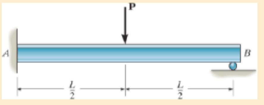
Chapter 12.7, Problem 12.102P
Determine the reactions at the supports A and B, then draw the shear and moment diagrams. El is constant.
Expert Solution & Answer

Learn your wayIncludes step-by-step video

schedule08:37
Students have asked these similar questions
Find the reaction force in x if Ain = 0.301 m^2, Aout = 0.177 m^2, p_in = 1.338 atm, Q = 0.669 m^3/s, and α = 37.183 degrees
Problem 5: Three-Force Equilibrium
A structural connection at point O is in equilibrium under the
action of three forces.
•
•
.
Member A applies a force of 9 kN vertically upward along
the y-axis.
Member B applies an unknown force F at the angle shown.
Member C applies an unknown force T along its length at
an angle shown.
Determine the magnitudes of forces F and T required for
equilibrium, assuming 0 = 90°
y
9 kN
A
Problem 19: Determine the force in members HG, HE, and DE of the truss, and state if the
members are in tension or compression.
4 ft
K
J
I
H
G
B
C
D
E
F
-3 ft
-3 ft 3 ft 3 ft 3 ft-
1500 lb 1500 lb 1500 lb 1500 lb 1500 lb
Chapter 12 Solutions
Mechanics of Materials
Ch. 12.2 - In each case, determine the internal bending...Ch. 12.2 - Determine the slope and deflection of end A of the...Ch. 12.2 - Determine the slope and deflection of end A of the...Ch. 12.2 - Determine the slope of end A of the cantilevered...Ch. 12.2 - Determine the maximum deflection of the simply...Ch. 12.2 - Determine the maximum deflection of the simply...Ch. 12.2 - Determine the slope of the simply supported beam...Ch. 12.2 - An L2 steel strap having a thickness of 0.125 in....Ch. 12.2 - The L2 steel blade of the band saw wraps around...Ch. 12.2 - A picture is taken of a man performing a pole...
Ch. 12.2 - Prob. 12.4PCh. 12.2 - 12-5. Determine the deflection of end C of the...Ch. 12.2 - Prob. 12.6PCh. 12.2 - Prob. 12.7PCh. 12.2 - Determine the equations of the elastic curve using...Ch. 12.2 - Determine the equations of the elastic curve for...Ch. 12.2 - 12-10. Determine the equations of the elastic...Ch. 12.2 - 12-11. Determine the deflection at the center of...Ch. 12.2 - Prob. 12.12PCh. 12.2 - Determine the maximum deflection of the beam and...Ch. 12.2 - The simply supported shaft has a moment of inertia...Ch. 12.2 - 12-15. The two wooden meter sticks are separated...Ch. 12.2 - Prob. 12.16PCh. 12.2 - Prob. 12.17PCh. 12.2 - The bar is supported by a roller constraint at B,...Ch. 12.2 - Determine the deflection at B of the bar in Prob....Ch. 12.2 - Determine the equations of the elastic curve using...Ch. 12.2 - Determine the maximum deflection of the solid...Ch. 12.2 - Determine the elastic curve for the cantilevered...Ch. 12.2 - Determine the equations of the elastic curve using...Ch. 12.2 - Determine the equations of the elastic curve using...Ch. 12.2 - The floor beam of the airplane is subjected to the...Ch. 12.2 - Determine the maximum deflection of the simply...Ch. 12.2 - Prob. 12.27PCh. 12.2 - Determine the slope at end B and the maximum...Ch. 12.2 - Determine the equation of the elastic curve using...Ch. 12.2 - Determine the equations of the elastic curve using...Ch. 12.3 - The shaft is supported at A by a journal bearing...Ch. 12.3 - The shaft supports the two pulley loads shown....Ch. 12.3 - 12-33. Determine the equation of the elastic...Ch. 12.3 - Determine the equation of the elastic curve, the...Ch. 12.3 - The beam is subjected to the load shown. Determine...Ch. 12.3 - Determine the equation of the elastic curve, the...Ch. 12.3 - Determine the equation of the elastic curve and...Ch. 12.3 - 12-38. The beam is subjected to the loads shown....Ch. 12.3 - Determine the maximum deflection of the...Ch. 12.3 - Determine the slope at A and the deflection of end...Ch. 12.3 - Determine the maximum deflection in region AB of...Ch. 12.3 - Prob. 12.42PCh. 12.3 - Prob. 12.43PCh. 12.3 - Prob. 12.44PCh. 12.3 - Prob. 12.45PCh. 12.3 - Prob. 12.46PCh. 12.3 - 12-47. The shaft is made of steel and has a...Ch. 12.3 - Prob. 12.48PCh. 12.3 - Determine the displacement at C and the slope at...Ch. 12.3 - Determine the equations of the slope and elastic...Ch. 12.4 - Determine the slope and deflection of end A of the...Ch. 12.4 - Determine the slope and deflection of end A of the...Ch. 12.4 - Determine the slope and deflection of end A of the...Ch. 12.4 - Determine the slope and deflection at A of the...Ch. 12.4 - Prob. 12.11FPCh. 12.4 - Determine the maximum deflection of the simply...Ch. 12.4 - Determine the slope and deflection at C. El is...Ch. 12.4 - Determine the slope and deflection at C. El is...Ch. 12.4 - Determine the deflection of end B of the...Ch. 12.4 - Prob. 12.54PCh. 12.4 - The composite simply supported steel shaft is...Ch. 12.4 - Prob. 12.56PCh. 12.4 - Prob. 12.57PCh. 12.4 - Determine the deflection at C and the slope of the...Ch. 12.4 - Prob. 12.59PCh. 12.4 - Prob. 12.60PCh. 12.4 - Determine the position a of the roller support B...Ch. 12.4 - Prob. 12.62PCh. 12.4 - Determine the slope and the deflection of end B of...Ch. 12.4 - Prob. 12.64PCh. 12.4 - Determine the slope at A and the displacement at...Ch. 12.4 - Determine the deflection at C and the slopes at...Ch. 12.4 - Determine the maximum deflection within region AB....Ch. 12.4 - Determine the slope at A and the maximum...Ch. 12.4 - Determine the slope at C and the deflection at B....Ch. 12.4 - Determine the slope at A and the maximum...Ch. 12.4 - Prob. 12.71PCh. 12.4 - Prob. 12.72PCh. 12.4 - Prob. 12.73PCh. 12.4 - The rod is constructed from two shafts for which...Ch. 12.4 - Prob. 12.75PCh. 12.4 - Determine the slope at point A and the maximum...Ch. 12.4 - Determine the position a of roller support B in...Ch. 12.4 - Determine the slope at B and deflection at C. El...Ch. 12.4 - Prob. 12.79PCh. 12.4 - Prob. 12.80PCh. 12.4 - Prob. 12.81PCh. 12.4 - Determine the maximum deflection of the beam. El...Ch. 12.5 - The W10 15 cantilevered beam is made of A-36...Ch. 12.5 - The W10 15 cantilevered beam is made of A-36...Ch. 12.5 - 12-85. Determine the slope and deflection at end C...Ch. 12.5 - 12-86. Determine the slope at A and the deflection...Ch. 12.5 - Prob. 12.87PCh. 12.5 - Prob. 12.88PCh. 12.5 - 12-89. The W8 × 24 simply supported beam is made...Ch. 12.5 - 12-90. The simply supported beam carries a uniform...Ch. 12.5 - Prob. 12.91PCh. 12.5 - *12-92. The W10 × 30 cantilevered beam is made of...Ch. 12.5 - The rod is pinned at its end A and attached to a...Ch. 12.5 - Prob. 12.94PCh. 12.5 - The pipe assembly consists of three equal-sized...Ch. 12.5 - *12-96. The framework consists of two A992 steel...Ch. 12.5 - Prob. 12.97PCh. 12.5 - 12-98. Determine the vertical deflection at the...Ch. 12.7 - Determine the reactions at the supports A and B,...Ch. 12.7 - Prob. 12.100PCh. 12.7 - Determine the reactions at the supports A, B, and...Ch. 12.7 - Determine the reactions at the supports A and B,...Ch. 12.7 - Determine the reactions at the supports A and B,...Ch. 12.7 - Prob. 12.104PCh. 12.7 - 12-105. Use discontinuity functions and determine...Ch. 12.7 - Determine the reactions at the support A and B. EI...Ch. 12.7 - 12-107. Determine the reactions at pin support A...Ch. 12.7 - Determine the moment reactions at the supports A...Ch. 12.7 - The beam has a constant E1I1 and is supported by...Ch. 12.7 - The beam is supported by a pin at A, a roller at...Ch. 12.8 - Determine the moment reactions at the supports A...Ch. 12.8 - Prob. 12.112PCh. 12.8 - Determine the vertical reaction at the journal...Ch. 12.8 - Determine the reactions at the supports A and B,...Ch. 12.8 - Prob. 12.115PCh. 12.8 - Determine the vertical reaction at the journal...Ch. 12.9 - Determine the reactions at the fixed support A and...Ch. 12.9 - Determine the reactions at the fixed support A and...Ch. 12.9 - Determine the reactions at the fixed support A and...Ch. 12.9 - Determine the reaction at the roller B. EI is...Ch. 12.9 - Determine the reaction at the roller B. EI is...Ch. 12.9 - Determine the reaction at the roller support B if...Ch. 12.9 - Determine the reactions at the journal bearing...Ch. 12.9 - Prob. 12.118PCh. 12.9 - 12-119. Determine the reactions at the supports A,...Ch. 12.9 - Prob. 12.120PCh. 12.9 - 12-121. Determine the deflection at the end B of...Ch. 12.9 - Determine the reactions at the supports A and B....Ch. 12.9 - Prob. 12.123PCh. 12.9 - Before the uniform distributed load is applied to...Ch. 12.9 - The fixed supported beam AB is strengthened using...Ch. 12.9 - 12-126. Determine the force in the spring. EI is...Ch. 12.9 - The beam is supported by the bolted supports at...Ch. 12.9 - Each of the two members is made from 6061-T6...Ch. 12.9 - The beam is made from a soft linear elastic...Ch. 12.9 - Prob. 12.130PCh. 12.9 - 12–131. The 1-in -diameter A-36 steel shaft is...Ch. 12.9 - Prob. 12.132PCh. 12 - Determine the equation of the elastic curve. Use...Ch. 12 - Draw the bending-moment diagram for the shaft and...Ch. 12 - Determine the moment reactions at the supports A...Ch. 12 - Specify the slope at A and the maximum deflection....Ch. 12 - Determine the maximum deflection between the...Ch. 12 - Determine the slope at B and the deflection at C....Ch. 12 - Determine the reactions, then draw the shear and...Ch. 12 - El is constant.Ch. 12 - Using the method of superposition, determine the...Ch. 12 - The rim on the flywheel has a thickness t, width...
Additional Engineering Textbook Solutions
Find more solutions based on key concepts
7.13* For a bearing
DE = NUS 5 53’56 ”WT and angles to the right, compute the bearing of PG if angle
DEF 2 88°...
Elementary Surveying: An Introduction To Geomatics (15th Edition)
Write some Java code to create an output stream of type ObjectOutputStream that is named to File and is connect...
Java: An Introduction to Problem Solving and Programming (8th Edition)
State whether each of the following is true or false. A set of statements contained within a pair of parenthese...
Java How to Program, Early Objects (11th Edition) (Deitel: How to Program)
What is the importance of modeling in engineering? How are the mathematical models for engineering processes pr...
HEAT+MASS TRANSFER:FUND.+APPL.
Describe a method that can be used to gather a piece of data such as the users age.
Web Development and Design Foundations with HTML5 (8th Edition)
What is the general problem with static scoping?
Concepts Of Programming Languages
Knowledge Booster


Learn more about
Need a deep-dive on the concept behind this application? Look no further. Learn more about this topic, mechanical-engineering and related others by exploring similar questions and additional content below.Similar questions
- Problem 14: Determine the reactions at the pin A, and the tension in cord. Neglect the thickness of the beam. F1=26kN F2 13 12 80° -2m 3marrow_forwardProblem 22: Determine the force in members GF, FC, and CD of the bridge truss and state if the members are in tension or compression. F 15 ft B D -40 ft 40 ft -40 ft 40 ft- 5 k 10 k 15 k 30 ft Earrow_forwardProblem 20: Determine the force in members BC, HC, and HG. After the truss is sectioned use a single equation of equilibrium for the calculation of each force. State if the members are in tension or compression. 5 kN 4 kN 4 kN 3 kN 2 kN B D E F 3 m -5 m- -5 m- 5 m 5 m-arrow_forward
- An experimental setup is being built to study the flow in a large water main (i.e., a large pipe). The water main is expected to convey a discharge (Qp). The experimental tube will be built at a length scale of 1/20 of the actual water main. After building the experimental setup, the pressure drop per unit length in the model tube (APm/Lm) is measured. Problem (19): Given the value of Qp [m³/s], and assuming Reynolds number similitude between the water main and experimental tube, calculate the flow rate in the model tube (Qm) in [lit/s]. = 30.015 m^3/sarrow_forwardProblem 11: The lamp has a weight of 15 lb and is supported by the six cords connected together as shown. Determine the tension in each cord and the angle 0 for equilibrium. Cord BC is horizontal. E 30° B 60° Aarrow_forwardProblem 10: If the bucket weighs 50 lb, determine the tension developed in each of the wires. B $30° 5 E D 130°arrow_forward
- Problem 3: Four-Force Equilibrium Knowing the forces in members A and C, determine the force of B and D, assuming the system is in equilibrium. A structural joint is held in equilibrium by four forces acting along different members. • Member A applies a force of 4 kN at an angle of 60° above the positive x-axis. • Member C applies a force of 2 kN horizontally to the left along the x-axis. • Member B applies an unknown force along the horizontal direction. • Member D applies an unknown force at an angle of 45° above the negative x-axis. Determine the forces in members B and D, assuming the system is in static equilibrium. 4 kN 2 kN C 45° A D 60° FB Barrow_forwardProblem 18: Determine the force in each member of the truss. State if the members are in tension or compression. 3 ft 3 ft 3 ft B D 4 ft 4 ft. 130 lb Earrow_forwardProblem 16: Determine the force in each of the member of the truss and state if the members are in tension or compression. Set P₁ = 10 kN, P2 = 8 kN. 2 m G F E A A 1 m B 2 m 1 m P1 Darrow_forward
- Problem 7: Determine the force in each cord for equilibrium of the 60-kg bucket. D E 4 m 4 m B 3 m- 3 m- 3 m.arrow_forwardProblem 15: Determine the reactions at the pin A and the tension in cord BC. Set F = 40 kN. Neglect the thickness of the beam. 26 kN F 13 12 -2 m 4 m B 4arrow_forwardProblem 21: Determine the force in members EF, CF, and BC and state if the members are in tension or compression. 1.5 m 4 kN E D 8 kN B 2 m 2 marrow_forward
arrow_back_ios
SEE MORE QUESTIONS
arrow_forward_ios
Recommended textbooks for you
 Elements Of ElectromagneticsMechanical EngineeringISBN:9780190698614Author:Sadiku, Matthew N. O.Publisher:Oxford University Press
 Mechanics of Materials (10th Edition)Mechanical EngineeringISBN:9780134319650Author:Russell C. HibbelerPublisher:PEARSON
 Thermodynamics: An Engineering ApproachMechanical EngineeringISBN:9781259822674Author:Yunus A. Cengel Dr., Michael A. BolesPublisher:McGraw-Hill Education
 Control Systems EngineeringMechanical EngineeringISBN:9781118170519Author:Norman S. NisePublisher:WILEY
 Mechanics of Materials (MindTap Course List)Mechanical EngineeringISBN:9781337093347Author:Barry J. Goodno, James M. GerePublisher:Cengage Learning
 Engineering Mechanics: StaticsMechanical EngineeringISBN:9781118807330Author:James L. Meriam, L. G. Kraige, J. N. BoltonPublisher:WILEY
Elements Of Electromagnetics
Mechanical Engineering
ISBN:9780190698614
Author:Sadiku, Matthew N. O.
Publisher:Oxford University Press
Mechanics of Materials (10th Edition)
Mechanical Engineering
ISBN:9780134319650
Author:Russell C. Hibbeler
Publisher:PEARSON
Thermodynamics: An Engineering Approach
Mechanical Engineering
ISBN:9781259822674
Author:Yunus A. Cengel Dr., Michael A. Boles
Publisher:McGraw-Hill Education
Control Systems Engineering
Mechanical Engineering
ISBN:9781118170519
Author:Norman S. Nise
Publisher:WILEY
Mechanics of Materials (MindTap Course List)
Mechanical Engineering
ISBN:9781337093347
Author:Barry J. Goodno, James M. Gere
Publisher:Cengage Learning
Engineering Mechanics: Statics
Mechanical Engineering
ISBN:9781118807330
Author:James L. Meriam, L. G. Kraige, J. N. Bolton
Publisher:WILEY
Understanding Shear Force and Bending Moment Diagrams; Author: The Efficient Engineer;https://www.youtube.com/watch?v=C-FEVzI8oe8;License: Standard YouTube License, CC-BY
Bending Stress; Author: moodlemech;https://www.youtube.com/watch?v=9QIqewkE6xM;License: Standard Youtube License