
Mechanics of Materials
9th Edition
ISBN: 9780133254426
Author: Russell C. Hibbeler
Publisher: Prentice Hall
expand_more
expand_more
format_list_bulleted
Videos
Textbook Question
Chapter 12.2, Problem 12.3P
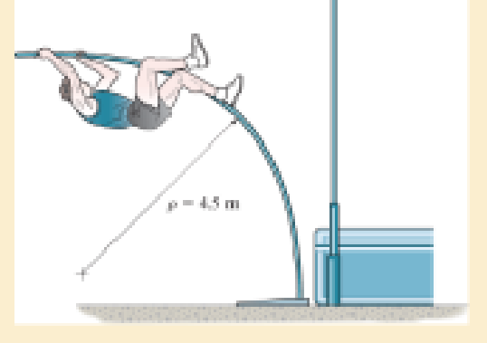
A picture is taken of a man performing a pole vault, and the minimum radius of curvature of the pole is estimated by measurement to be 4.5 m. If the pole is 40 mm in diameter and it is made of a glass-reinforced plastic for which Eg = 131 GPa, determine the maximum bending stress in the pole.
Prob. 12–3
Expert Solution & Answer

Learn your wayIncludes step-by-step video

schedule02:17
Students have asked these similar questions
For the first part: d = 4 cm, and Q = 15 Liters/s. For the second part Q = 6 Liters/s, and D = 80 cm
Q.2: (15 Marks)
=
1400
For the following system, determine the first natural frequency using Dunkerley's equation,
Given that the disk has moment of inertia J = 2 kg.m², the shaft has G = 20 GPa, p
kg/m³, polar moment of cross-sectional area of the shaft Ip = 8×10⁸ m².
500 mm
220 mm
k=200 N/m
FOF
m=1 kg
14.14
56.56. W
сл
1 Revolute four-bar mechanism, AB=60mm, BC=130mm, CD=140mm, AD=200mm,
Chapter 12 Solutions
Mechanics of Materials
Ch. 12.2 - In each case, determine the internal bending...Ch. 12.2 - Determine the slope and deflection of end A of the...Ch. 12.2 - Determine the slope and deflection of end A of the...Ch. 12.2 - Determine the slope of end A of the cantilevered...Ch. 12.2 - Determine the maximum deflection of the simply...Ch. 12.2 - Determine the maximum deflection of the simply...Ch. 12.2 - Determine the slope of the simply supported beam...Ch. 12.2 - An L2 steel strap having a thickness of 0.125 in....Ch. 12.2 - The L2 steel blade of the band saw wraps around...Ch. 12.2 - A picture is taken of a man performing a pole...
Ch. 12.2 - Prob. 12.4PCh. 12.2 - 12-5. Determine the deflection of end C of the...Ch. 12.2 - Prob. 12.6PCh. 12.2 - Prob. 12.7PCh. 12.2 - Determine the equations of the elastic curve using...Ch. 12.2 - Determine the equations of the elastic curve for...Ch. 12.2 - 12-10. Determine the equations of the elastic...Ch. 12.2 - 12-11. Determine the deflection at the center of...Ch. 12.2 - Prob. 12.12PCh. 12.2 - Determine the maximum deflection of the beam and...Ch. 12.2 - The simply supported shaft has a moment of inertia...Ch. 12.2 - 12-15. The two wooden meter sticks are separated...Ch. 12.2 - Prob. 12.16PCh. 12.2 - Prob. 12.17PCh. 12.2 - The bar is supported by a roller constraint at B,...Ch. 12.2 - Determine the deflection at B of the bar in Prob....Ch. 12.2 - Determine the equations of the elastic curve using...Ch. 12.2 - Determine the maximum deflection of the solid...Ch. 12.2 - Determine the elastic curve for the cantilevered...Ch. 12.2 - Determine the equations of the elastic curve using...Ch. 12.2 - Determine the equations of the elastic curve using...Ch. 12.2 - The floor beam of the airplane is subjected to the...Ch. 12.2 - Determine the maximum deflection of the simply...Ch. 12.2 - Prob. 12.27PCh. 12.2 - Determine the slope at end B and the maximum...Ch. 12.2 - Determine the equation of the elastic curve using...Ch. 12.2 - Determine the equations of the elastic curve using...Ch. 12.3 - The shaft is supported at A by a journal bearing...Ch. 12.3 - The shaft supports the two pulley loads shown....Ch. 12.3 - 12-33. Determine the equation of the elastic...Ch. 12.3 - Determine the equation of the elastic curve, the...Ch. 12.3 - The beam is subjected to the load shown. Determine...Ch. 12.3 - Determine the equation of the elastic curve, the...Ch. 12.3 - Determine the equation of the elastic curve and...Ch. 12.3 - 12-38. The beam is subjected to the loads shown....Ch. 12.3 - Determine the maximum deflection of the...Ch. 12.3 - Determine the slope at A and the deflection of end...Ch. 12.3 - Determine the maximum deflection in region AB of...Ch. 12.3 - Prob. 12.42PCh. 12.3 - Prob. 12.43PCh. 12.3 - Prob. 12.44PCh. 12.3 - Prob. 12.45PCh. 12.3 - Prob. 12.46PCh. 12.3 - 12-47. The shaft is made of steel and has a...Ch. 12.3 - Prob. 12.48PCh. 12.3 - Determine the displacement at C and the slope at...Ch. 12.3 - Determine the equations of the slope and elastic...Ch. 12.4 - Determine the slope and deflection of end A of the...Ch. 12.4 - Determine the slope and deflection of end A of the...Ch. 12.4 - Determine the slope and deflection of end A of the...Ch. 12.4 - Determine the slope and deflection at A of the...Ch. 12.4 - Prob. 12.11FPCh. 12.4 - Determine the maximum deflection of the simply...Ch. 12.4 - Determine the slope and deflection at C. El is...Ch. 12.4 - Determine the slope and deflection at C. El is...Ch. 12.4 - Determine the deflection of end B of the...Ch. 12.4 - Prob. 12.54PCh. 12.4 - The composite simply supported steel shaft is...Ch. 12.4 - Prob. 12.56PCh. 12.4 - Prob. 12.57PCh. 12.4 - Determine the deflection at C and the slope of the...Ch. 12.4 - Prob. 12.59PCh. 12.4 - Prob. 12.60PCh. 12.4 - Determine the position a of the roller support B...Ch. 12.4 - Prob. 12.62PCh. 12.4 - Determine the slope and the deflection of end B of...Ch. 12.4 - Prob. 12.64PCh. 12.4 - Determine the slope at A and the displacement at...Ch. 12.4 - Determine the deflection at C and the slopes at...Ch. 12.4 - Determine the maximum deflection within region AB....Ch. 12.4 - Determine the slope at A and the maximum...Ch. 12.4 - Determine the slope at C and the deflection at B....Ch. 12.4 - Determine the slope at A and the maximum...Ch. 12.4 - Prob. 12.71PCh. 12.4 - Prob. 12.72PCh. 12.4 - Prob. 12.73PCh. 12.4 - The rod is constructed from two shafts for which...Ch. 12.4 - Prob. 12.75PCh. 12.4 - Determine the slope at point A and the maximum...Ch. 12.4 - Determine the position a of roller support B in...Ch. 12.4 - Determine the slope at B and deflection at C. El...Ch. 12.4 - Prob. 12.79PCh. 12.4 - Prob. 12.80PCh. 12.4 - Prob. 12.81PCh. 12.4 - Determine the maximum deflection of the beam. El...Ch. 12.5 - The W10 15 cantilevered beam is made of A-36...Ch. 12.5 - The W10 15 cantilevered beam is made of A-36...Ch. 12.5 - 12-85. Determine the slope and deflection at end C...Ch. 12.5 - 12-86. Determine the slope at A and the deflection...Ch. 12.5 - Prob. 12.87PCh. 12.5 - Prob. 12.88PCh. 12.5 - 12-89. The W8 × 24 simply supported beam is made...Ch. 12.5 - 12-90. The simply supported beam carries a uniform...Ch. 12.5 - Prob. 12.91PCh. 12.5 - *12-92. The W10 × 30 cantilevered beam is made of...Ch. 12.5 - The rod is pinned at its end A and attached to a...Ch. 12.5 - Prob. 12.94PCh. 12.5 - The pipe assembly consists of three equal-sized...Ch. 12.5 - *12-96. The framework consists of two A992 steel...Ch. 12.5 - Prob. 12.97PCh. 12.5 - 12-98. Determine the vertical deflection at the...Ch. 12.7 - Determine the reactions at the supports A and B,...Ch. 12.7 - Prob. 12.100PCh. 12.7 - Determine the reactions at the supports A, B, and...Ch. 12.7 - Determine the reactions at the supports A and B,...Ch. 12.7 - Determine the reactions at the supports A and B,...Ch. 12.7 - Prob. 12.104PCh. 12.7 - 12-105. Use discontinuity functions and determine...Ch. 12.7 - Determine the reactions at the support A and B. EI...Ch. 12.7 - 12-107. Determine the reactions at pin support A...Ch. 12.7 - Determine the moment reactions at the supports A...Ch. 12.7 - The beam has a constant E1I1 and is supported by...Ch. 12.7 - The beam is supported by a pin at A, a roller at...Ch. 12.8 - Determine the moment reactions at the supports A...Ch. 12.8 - Prob. 12.112PCh. 12.8 - Determine the vertical reaction at the journal...Ch. 12.8 - Determine the reactions at the supports A and B,...Ch. 12.8 - Prob. 12.115PCh. 12.8 - Determine the vertical reaction at the journal...Ch. 12.9 - Determine the reactions at the fixed support A and...Ch. 12.9 - Determine the reactions at the fixed support A and...Ch. 12.9 - Determine the reactions at the fixed support A and...Ch. 12.9 - Determine the reaction at the roller B. EI is...Ch. 12.9 - Determine the reaction at the roller B. EI is...Ch. 12.9 - Determine the reaction at the roller support B if...Ch. 12.9 - Determine the reactions at the journal bearing...Ch. 12.9 - Prob. 12.118PCh. 12.9 - 12-119. Determine the reactions at the supports A,...Ch. 12.9 - Prob. 12.120PCh. 12.9 - 12-121. Determine the deflection at the end B of...Ch. 12.9 - Determine the reactions at the supports A and B....Ch. 12.9 - Prob. 12.123PCh. 12.9 - Before the uniform distributed load is applied to...Ch. 12.9 - The fixed supported beam AB is strengthened using...Ch. 12.9 - 12-126. Determine the force in the spring. EI is...Ch. 12.9 - The beam is supported by the bolted supports at...Ch. 12.9 - Each of the two members is made from 6061-T6...Ch. 12.9 - The beam is made from a soft linear elastic...Ch. 12.9 - Prob. 12.130PCh. 12.9 - 12–131. The 1-in -diameter A-36 steel shaft is...Ch. 12.9 - Prob. 12.132PCh. 12 - Determine the equation of the elastic curve. Use...Ch. 12 - Draw the bending-moment diagram for the shaft and...Ch. 12 - Determine the moment reactions at the supports A...Ch. 12 - Specify the slope at A and the maximum deflection....Ch. 12 - Determine the maximum deflection between the...Ch. 12 - Determine the slope at B and the deflection at C....Ch. 12 - Determine the reactions, then draw the shear and...Ch. 12 - El is constant.Ch. 12 - Using the method of superposition, determine the...Ch. 12 - The rim on the flywheel has a thickness t, width...
Additional Engineering Textbook Solutions
Find more solutions based on key concepts
In the following exercises, write a program to carry out the task. The program should use variables for each of...
Introduction To Programming Using Visual Basic (11th Edition)
How do honing stones differ from grinding wheels?
Degarmo's Materials And Processes In Manufacturing
If the Vole executes an instruction every microsecond (a millionth of a second), how long does it take to compl...
Computer Science: An Overview (13th Edition) (What's New in Computer Science)
Prime Numbers A prime number is a number that is only evenly divisible by itself and 1. For example, the number...
Starting Out with Python (4th Edition)
Describe two properties that each candidate key must satisfy.
Modern Database Management
How do you determine the number of bytes that a file contains?
Starting Out with C++ from Control Structures to Objects (9th Edition)
Knowledge Booster


Learn more about
Need a deep-dive on the concept behind this application? Look no further. Learn more about this topic, mechanical-engineering and related others by exploring similar questions and additional content below.Similar questions
- CORRECT AND DETAILED HANDWRITTEN SOLUTION WITH FBD ONLY. I WILL UPVOTE THANK YOU. CORRECT ANSWER IS ALREADY PROVIDED. The roof truss shown carries roof loads, where P = 10 kN. The truss is consisting of circular arcs top andbottom chords with radii R + h and R, respectively.Given: h = 1.2 m, R = 10 m, s = 2 m.Allowable member stresses:Tension = 250 MPaCompression = 180 MPa1. If member KL has square section, determine the minimum dimension (mm).2. If member KL has circular section, determine the minimum diameter (mm).3. If member GH has circular section, determine the minimum diameter (mm).ANSWERS: (1) 31.73 mm; (2) 35.81 mm; (3) 18.49 mmarrow_forwardCORRECT AND DETAILED HANDWRITTEN SOLUTION WITH FBD ONLY. I WILL UPVOTE THANK YOU. CORRECT ANSWER IS ALREADY PROVIDED. The cantilevered spandrel beam shown whose depth tapers from d1 to d2, has a constant width of 120mm. It carries a triangularly distributed end reaction.Given: d1 = 600 mm, d2 = 120 mm, L = 1 m, w = 100 kN/m1. Calculate the maximum flexural stress at the support, in kN-m.2. Determine the distance (m), from the free end, of the section with maximum flexural stress.3. Determine the maximum flexural stress in the beam, in MPa.ANSWERS: (1) 4.630 MPa; (2) 905.8688 m; (3) 4.65 MPaarrow_forwardCORRECT AND DETAILED HANDWRITTEN SOLUTION WITH FBD ONLY. I WILL UPVOTE THANK YOU. CORRECT ANSWER IS ALREADY PROVIDED. A concrete wall retains water as shown. Assume that the wall is fixed at the base. Given: H = 3 m, t = 0.5m, Concrete unit weight = 23 kN/m3Unit weight of water = 9.81 kN/m3(Hint: The pressure of water is linearly increasing from the surface to the bottom with intensity 9.81d.)1. Find the maximum compressive stress (MPa) at the base of the wall if the water reaches the top.2. If the maximum compressive stress at the base of the wall is not to exceed 0.40 MPa, what is the maximum allowable depth(m) of the water?3. If the tensile stress at the base is zero, what is the maximum allowable depth (m) of the water?ANSWERS: (1) 1.13 MPa, (2) 2.0 m, (3) 1.20 marrow_forward
- CORRECT AND DETAILED HANDWRITTEN SOLUTION WITH FBD ONLY. I WILL UPVOTE THANK YOU. CORRECT ANSWER IS ALREADY PROVIDED. A short plate is attached to the center of the shaft as shown. The bottom of the shaft is fixed to the ground.Given: a = 75 mm, h = 125 mm, D = 38 mmP1 = 24 kN, P2 = 28 kN1. Calculate the maximum torsional stress in the shaft, in MPa.2. Calculate the maximum flexural stress in the shaft, in MPa.3. Calculate the maximum horizontal shear stress in the shaft, in MPa.ANSWERS: (1) 167.07 MPa; (2) 679.77 MPa; (3) 28.22 MPaarrow_forwardA counter flow double pipe heat exchanger is being used to cool hot oil from 320°F to 285°F using cold water. The water, which flows through the inner tube, enters the heat exchanger at 70°F and leaves at 175°F. The inner tube is ¾-std type L copper. The overall heat transfer coefficient based on the outside diameter of the inner tube is 140 Btu/hr-ft2-°F. Design conditions call for a total heat transfer duty (heat transfer rate between the two fluids) of 20,000 Btu/hr. Determine the required length of this heat exchanger (ft).arrow_forward! Required information A one-shell-pass and eight-tube-passes heat exchanger is used to heat glycerin (cp=0.60 Btu/lbm.°F) from 80°F to 140°F by hot water (Cp = 1.0 Btu/lbm-°F) that enters the thin-walled 0.5-in-diameter tubes at 175°F and leaves at 120°F. The total length of the tubes in the heat exchanger is 400 ft. The convection heat transfer coefficient is 4 Btu/h-ft²°F on the glycerin (shell) side and 70 Btu/h-ft²°F on the water (tube) side. NOTE: This is a multi-part question. Once an answer is submitted, you will be unable to return to this part. Determine the rate of heat transfer in the heat exchanger before any fouling occurs. Correction factor F 1.0 10 0.9 0.8 R=4.0 3.0 2.0.15 1.0 0.8.0.6 0.4 0.2 0.7 0.6 R= T1-T2 12-11 0.5 12-11 0 0.1 0.2 0.3 0.4 0.5 0.6 0.7 0.8 0.9 1.0 (a) One-shell pass and 2, 4, 6, etc. (any multiple of 2), tube passes P= T₁-11 The rate of heat transfer in the heat exchanger is Btu/h.arrow_forward
- ! Required information Air at 25°C (cp=1006 J/kg.K) is to be heated to 58°C by hot oil at 80°C (cp = 2150 J/kg.K) in a cross-flow heat exchanger with air mixed and oil unmixed. The product of heat transfer surface area and the overall heat transfer coefficient is 750 W/K and the mass flow rate of air is twice that of oil. NOTE: This is a multi-part question. Once an answer is submitted, you will be unable to return to this part. Air Oil 80°C Determine the effectiveness of the heat exchanger.arrow_forwardIn an industrial facility, a counter-flow double-pipe heat exchanger uses superheated steam at a temperature of 155°C to heat feed water at 30°C. The superheated steam experiences a temperature drop of 70°C as it exits the heat exchanger. The water to be heated flows through the heat exchanger tube of negligible thickness at a constant rate of 3.47 kg/s. The convective heat transfer coefficient on the superheated steam and water side is 850 W/m²K and 1250 W/m²K, respectively. To account for the fouling due to chemical impurities that might be present in the feed water, assume a fouling factor of 0.00015 m²-K/W for the water side. The specific heat of water is determined at an average temperature of (30 +70)°C/2 = 50°C and is taken to be J/kg.K. Cp= 4181 Water Steam What would be the required heat exchanger area in case of parallel-flow arrangement? The required heat exchanger area in case of parallel-flow arrangement is 1m².arrow_forwardA single-pass crossflow heat exchanger is used to cool jacket water (cp = 1.0 Btu/lbm.°F) of a diesel engine from 190°F to 140°F, using air (Cp = 0.245 Btu/lbm.°F) at inlet temperature of 90°F. Both air flow and water flow are unmixed. If the water and air mass flow rates are 85500 lbm/h and 400,000 lbm/h, respectively, determine the log mean temperature difference for this heat exchanger. Assume the correction factor F to be 0.92. Air flow (unmixed) Water flow (unmixed) The log mean temperature difference of the heat exchanger is °F.arrow_forward
- using the theorem of three moments, find all the reactions and supports, I need concise calculations only. the answers are at the bottom, I need concise steps and minimal explanationsarrow_forwardIn an industrial facility, a counter-flow double-pipe heat exchanger uses superheated steam at a temperature of 155°C to heat feed water at 30°C. The superheated steam experiences a temperature drop of 70°C as it exits the heat exchanger. The water to be heated flows through the heat exchanger tube of negligible thickness at a constant rate of 3.47 kg/s. The convective heat transfer coefficient on the superheated steam and water side is 850 W/m²K and 1250 W/m²K, respectively. To account for the fouling due to chemical impurities that might be present in the feed water, assume a fouling factor of 0.00015 m² K/W for the water side. The specific heat of water is determined at an average temperature of (30+70)°C/2 = 50°C and is taken to be Cp J/kg-K. Water Steam Determine the heat exchanger area required to maintain the exit temperature of the water to a minimum of 70°C. The heat exchanger area required isarrow_forwardStress, ksi 160 72 150- 140 80 70 ༄ ྃ ༈ ཎྜ རྦ ༅ ཎྜ ྣཧྨ ➢ 130 120 110 100 90 2.0 2.8 3.6 4.4 5 Wire diameter, mm 6.0 6.8 2 7.6 8.4 Compression and extension springs. ASTM A227 Class II Light service Average service 0.020 0.060 0.100 0.140 0.180 0.220 0.260 0.300 0.340 0.380 0.420 0.460 0.500 Wire diameter, in Torsional stress due to initial tension, ksi 10 ४ 20 Preferred range 100 Stress, MPa 9.2 10.0 10.8 11.6 12.4 1100 1035 965 895 825 760 Severe service 690 620 550 50 150 3456789 10 11 12 13 14 15 16 Spring index, C = DJD FIGURE 18-21 Recommended torsional shear stress in an extension spring due to initial tension (Data from Associated Spring, Barnes Group, Inc.) 50 200 485 Stress, MPaarrow_forward
arrow_back_ios
SEE MORE QUESTIONS
arrow_forward_ios
Recommended textbooks for you
 Elements Of ElectromagneticsMechanical EngineeringISBN:9780190698614Author:Sadiku, Matthew N. O.Publisher:Oxford University Press
 Mechanics of Materials (10th Edition)Mechanical EngineeringISBN:9780134319650Author:Russell C. HibbelerPublisher:PEARSON
 Thermodynamics: An Engineering ApproachMechanical EngineeringISBN:9781259822674Author:Yunus A. Cengel Dr., Michael A. BolesPublisher:McGraw-Hill Education
 Control Systems EngineeringMechanical EngineeringISBN:9781118170519Author:Norman S. NisePublisher:WILEY
 Mechanics of Materials (MindTap Course List)Mechanical EngineeringISBN:9781337093347Author:Barry J. Goodno, James M. GerePublisher:Cengage Learning
 Engineering Mechanics: StaticsMechanical EngineeringISBN:9781118807330Author:James L. Meriam, L. G. Kraige, J. N. BoltonPublisher:WILEY
Elements Of Electromagnetics
Mechanical Engineering
ISBN:9780190698614
Author:Sadiku, Matthew N. O.
Publisher:Oxford University Press
Mechanics of Materials (10th Edition)
Mechanical Engineering
ISBN:9780134319650
Author:Russell C. Hibbeler
Publisher:PEARSON
Thermodynamics: An Engineering Approach
Mechanical Engineering
ISBN:9781259822674
Author:Yunus A. Cengel Dr., Michael A. Boles
Publisher:McGraw-Hill Education
Control Systems Engineering
Mechanical Engineering
ISBN:9781118170519
Author:Norman S. Nise
Publisher:WILEY
Mechanics of Materials (MindTap Course List)
Mechanical Engineering
ISBN:9781337093347
Author:Barry J. Goodno, James M. Gere
Publisher:Cengage Learning
Engineering Mechanics: Statics
Mechanical Engineering
ISBN:9781118807330
Author:James L. Meriam, L. G. Kraige, J. N. Bolton
Publisher:WILEY
Mechanics of Materials Lecture: Beam Design; Author: UWMC Engineering;https://www.youtube.com/watch?v=-wVs5pvQPm4;License: Standard Youtube License