
Videos
An adiabatic 0.2-m3 storage tank that is initially evacuated is connected to a supply line that carries nitrogen at 225 K and 10 MPa. A valve is opened, and nitrogen flows into the tank from the supply line. The valve is closed when the pressure in the tank reaches 10 MPa. Determine the final temperature in the tank (a) treating nitrogen as an ideal gas, and (b) using generalized charts. Compare your results to the actual value of 293 K.
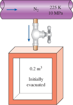
FIGURE P12–101
(a)
The final temperature in the tank by treating nitrogen as an ideal gas and compare the result to the actual value of
Answer to Problem 92RP
The final temperature in the tank by treating nitrogen as an ideal gas is
Explanation of Solution
Write the equation of mass balance.
Here, the inlet mass is
The change in mass of the system for the control volume is expressed as,
Here, the suffixes 1 and 2 indicates the initial and final states of the system.
Consider the given insulated tank as the control volume.
The valve is closed when the pressure in tank reaches to
Rewrite the Equation (I) as follows.
Write the energy balance equation.
Here, the heat transfer is
Since the tank is adiabatic, there is no heat transfer i.e.
The Equation (III) reduced as follows.
Substitute
Express the Equation (V) in molar basis.
Here, the molar mass of nitrogen is
Conclusion:
The inlet condition of the nitrogen is
While considering the nitrogen as the ideal gas, its enthalpy is solely depends on temperature.
Refer Table A-18, “Ideal-gas properties of nitrogen,
The molar enthalpy of nitrogen corresponding to the temperature of
Refer Equation (VI).
The final temperature of the nitrogen is expressed as follows.
Refer Table A-18, “Ideal-gas properties of nitrogen,
The final temperature
Thus, the final temperature in the tank by treating nitrogen as an ideal gas is
The percentage error with the actual temperature value of
The error associated is
(b)
The final temperature in the tank by using generalized departure charts.
Answer to Problem 92RP
The final temperature in the tank by using generalized departure charts is
Explanation of Solution
Refer Table A-1, “Molar mass, gas constant, and critical-point properties”.
The critical temperature and pressure of nitrogen gas is as follows.
The reduced pressure
At inlet:
Refer Figure A-29, “Generalized enthalpy departure chart”.
The enthalpy departure factor
Write formula for enthalpy departure factor
Here, the inlet molar enthalpy at ideal gas state is
Rearrange the Equation (I) to obtain
Write the formula for molar enthalpy at final state
Write the formula for molar internal energy at final state.
Here, the compressibility factor is
The universal gas constant
Conclusion:
Refer part (a) answer for
Substitute
Refer Equation (VI).
It is given that the actual final temperature of nitrogen is
Consider the exit temperature
The reduced pressure
Refer Figure A-29, “Generalized enthalpy departure chart”.
The enthalpy departure factor
Refer Figure A-15, “Nelson–Obert generalized compressibility chart”.
The compressibility factor
Refer Table A-18, “Ideal-gas properties of nitrogen,
The final molar enthalpy of nitrogen
Substitute
Substitute
Express interpolation formula to determine the final temperature
Substitute
Thus, the final temperature in the tank by using generalized departure charts is
The percentage error with the actual temperature value of
The error associated is
Want to see more full solutions like this?
Chapter 12 Solutions
THERMODYNAMICS(SI UNITS,INTL.ED)EBOOK>I


- Q4 The two solid shafts are connected by gears as shown and are made of a steel for which the allowable shearing stress is 7000 psi. Knowing the diameters of the two shafts are, respectively, dBC determine the largest torque Tc that can be applied at C. 4 and dEF dBC=Last 1 student ID+3 inch dEF=Last 1 student ID+1 inch 7 R=Last 1 Student ID+5 inch 9 R B Tc 2.5 in. E TF Harrow_forwardExperiment تكنولوجيا السيارات - Internal Forced convenction Heat transfer Air Flow through Rectangular Duct. objective: Study the convection heat transfer of air flow through rectangular duct. Valve Th Top Dead Centre Exhaust Valve Class CP. N; ~ RIVavg Ti K 2.11 Te To 18.8 21.3 45.8 Nath Ne Pre Calculations:. Q = m cp (Te-Ti) m: Varg Ac Acca*b Q=hexp As (Ts-Tm) 2 2.61 18.5 20.846.3 Tm = Te-Ti = 25 AS-PL = (a+b)*2*L Nu exp= Re-Vavy D heep Dh k 2ab a+b Nu Dh the- (TS-Tm) Ts. Tmy Name / Nu exp Naxe بب ارتدان العشريarrow_forwardProcedure:1- Cartesian system, 2D3D,type of support2- Free body diagram3 - Find the support reactions4- If you find a negativenumber then flip the force5- Find the internal force3D∑Fx=0∑Fy=0∑Fz=0∑Mx=0∑My=0\Sigma Mz=02D\Sigma Fx=0\Sigma Fy=0\Sigma Mz=05- Use method of sectionand cut the elementwhere you want to findarrow_forward
- Procedure:1- Cartesian system, 2D3D,type of support2- Free body diagram3 - Find the support reactions4- If you find a negativenumber then flip the force5- Find the internal force3D∑Fx=0∑Fy=0∑Fz=0∑Mx=0∑My=0\Sigma Mz=02D\Sigma Fx=0\Sigma Fy=0\Sigma Mz=05- Use method of sectionand cut the elementwhere you want to findthe internal force andkeep either side of thearrow_forwardProcedure: 1- Cartesian system, 2D3D, type of support 2- Free body diagram 3 - Find the support reactions 4- If you find a negative number then flip the force 5- Find the internal force 3D ∑Fx=0 ∑Fy=0 ∑Fz=0 ∑Mx=0 ∑My=0 ΣMz=0 2D ΣFx=0 ΣFy=0 ΣMz=0 5- Use method of section and cut the element where you want to find the internal force and keep either side of thearrow_forwardProcedure:1- Cartesian system, 2D3D,type of support2- Free body diagram3 - Find the support reactions4- If you find a negativenumber then flip the force5- Find the internal force3D∑Fx=0∑Fy=0∑Fz=0∑Mx=0∑My=0\Sigma Mz=02D\Sigma Fx=0\Sigma Fy=0\Sigma Mz=05- Use method of sectionand cut the elementwhere you want to findthe internal force andkeep either side of thearrow_forward
- Procedure: 1- Cartesian system, 2(D)/(3)D, type of support 2- Free body diagram 3 - Find the support reactions 4- If you find a negative number then flip the force 5- Find the internal force 3D \sum Fx=0 \sum Fy=0 \sum Fz=0 \sum Mx=0 \sum My=0 \Sigma Mz=0 2D \Sigma Fx=0 \Sigma Fy=0 \Sigma Mz=0 5- Use method of section and cut the element where you want to find the internal force and keep either side of the sectionarrow_forwardProcedure: 1- Cartesian system, 2(D)/(3)D, type of support 2- Free body diagram 3 - Find the support reactions 4- If you find a negative number then flip the force 5- Find the internal force 3D \sum Fx=0 \sum Fy=0 \sum Fz=0 \sum Mx=0 \sum My=0 \Sigma Mz=0 2D \Sigma Fx=0 \Sigma Fy=0 \Sigma Mz=0 5- Use method of section and cut the element where you want to find the internal force and keep either side of the sectionarrow_forwardFor each system below with transfer function G(s), plot the pole(s) on the s-plane. and indicate whether the system is: (a) "stable" (i.e., a bounded input will always result in a bounded output), (b) "marginally stable," or (c) "unstable" Sketch a rough graph of the time response to a step input. 8 a) G(s) = 5-5 8 b) G(s) = c) G(s) = = s+5 3s + 8 s² - 2s +2 3s +8 d) G(s): = s²+2s+2 3s+8 e) G(s): = s² +9 f) G(s): 8 00 == Sarrow_forward
- Please answer the following question. Include all work and plase explain. Graphs are provided below. "Consider the Mg (Magnesium) - Ni (Nickel) phase diagram shown below. This phase diagram contains two eutectic reactions and two intermediate phases (Mg2Ni and MgNi2). At a temperature of 505oC, determine what the composition of an alloy would need to be to contain a mass fraction of 0.20 Mg and 0.80 Mg2Ni."arrow_forwardThe triangular plate, having a 90∘∘ angle at AA, supports the load PP = 370 lblb as shown in (Figure 1).arrow_forwardDesign a 4-bar linkage to carry the body in Figure 1 through the two positions P1 and P2 at the angles shown in the figure. Use analytical synthesis with the free choice values z = 1.075, q= 210°, ß2 = −27° for left side and s = 1.24, y= 74°, ½ = − 40° for right side. φ 1.236 P2 147.5° 210° 2.138 P1 Figure 1 Xarrow_forward
 Elements Of ElectromagneticsMechanical EngineeringISBN:9780190698614Author:Sadiku, Matthew N. O.Publisher:Oxford University Press
 Mechanics of Materials (10th Edition)Mechanical EngineeringISBN:9780134319650Author:Russell C. HibbelerPublisher:PEARSON
 Thermodynamics: An Engineering ApproachMechanical EngineeringISBN:9781259822674Author:Yunus A. Cengel Dr., Michael A. BolesPublisher:McGraw-Hill Education
 Control Systems EngineeringMechanical EngineeringISBN:9781118170519Author:Norman S. NisePublisher:WILEY
 Mechanics of Materials (MindTap Course List)Mechanical EngineeringISBN:9781337093347Author:Barry J. Goodno, James M. GerePublisher:Cengage Learning
 Engineering Mechanics: StaticsMechanical EngineeringISBN:9781118807330Author:James L. Meriam, L. G. Kraige, J. N. BoltonPublisher:WILEY