
Mechanics of Materials
11th Edition
ISBN: 9780137605460
Author: Russell C. Hibbeler
Publisher: Pearson Education (US)
expand_more
expand_more
format_list_bulleted
Concept explainers
Videos
Textbook Question
Chapter 12.5, Problem 83P
The W10 × 15 cantilevered beam is made of A-36 steel and is subjected to the loading shown. Determine the slope and displacement at its end B.
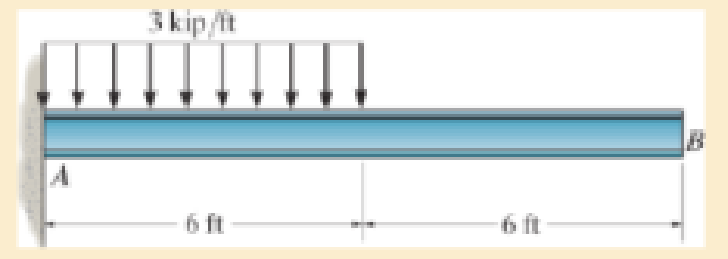
Prob. 12–83
Expert Solution & Answer

Learn your wayIncludes step-by-step video

schedule09:49
Students have asked these similar questions
In MATLAB write out a program to integrate the equations of motion of a rigid body. The inertia matrix is given by I = [125 0 0; 0 100 0; 0 0 75] which is a diagonal, where diag operator provides a matrix with given elements placed on its diagonal. Consider three cases where the body rotates 1 rad/sec about each principal axis. Integrate the resulting motion and study the angular rates and the resulting attitude (use any attitude coordinates). For each principal axis case, assume first that a pure spin about the principal axis is performed, and then repeat the simulation where a small 0.1 rad/sec motion is present about another principal axis. Discuss the stability of each motion. The code should produce a total of 6 simulations results when it is ran.
Q.
A strain gauge rosette that is attached to the surface of a stressed component
C). If the strain gauge rosette is of the D°
gives 3 readings (a = A, b = B, &c =
type (indicating the angle between each of the gauges), construct a Mohr's Strain
Circle overleaf. You should assume that gauge A is aligned along the x-axis.
Using the Mohr's Strain Circle calculate the:
[10 marks]
100 918 ucy evods gringiz ya
mwo quoy al etsede
39 926919
(i) principal strains (1, 2)?
(au) oniona
[5 marks]
(ii) principal angles (1, 2)?
You should measure these anticlockwise from the y-axis.
20
[5 marks]
(iii) maximum shear strain in the plane (ymax)?
Ex = Ea
Ey = εc
[5 marks]
(epol)
(apob) é
Ea = A = -210
2
B=E₁ = -50
E₁ = C = 340
D = 45°
bril
elled
✓A
bedivordan nemigas olloho shot on no eonsoup Imeneo
alubom shine sail-no viss ieqse sidetiva
bnat sabied
2
1)
Solve and show which is converage or diyverage
a = 2+(0.1)"
3
16) a =
n
1-2n
2)
a
=
In n
1+2n
17) a =
n
1-5n4
3)
an
=
n* +8n³
18) a =√4"n
n² -2n+1
n!
20) a =
4)
a₁ =
10
n-1
(Ina)
5)
a=1+(-1)"
21) a=
6)
a
7)
an
=
* = (12+) (1-1)
2n
(-1)+1
2n-1
3n+1
22) a=
3n-1
x"
23) a=
.x>0
2n+1
2n
3"x6"
8) a =
24) a =
n+1
π
9)
a = sin
2
sin n
10) an =
n
+
2 x n!
25) a = tanh(n)
n²
1
26) a = -sin-
2n-1
27) a = tan(n)
n
n
11) a =
2"
12) a =
n
13) a = 8/
+=(1+2)"
14) a =
15) a = √10n
In(n+1)
29) a =
n
30) an-√n²-1
1
28) a =
+
√2"
(In n)200
n
31) a=-
= 1 dx
nix
Chapter 12 Solutions
Mechanics of Materials
Ch. 12.2 - Determine the slope and deflection of end A of the...Ch. 12.2 - Determine the slope and deflection of end A of the...Ch. 12.2 - Determine the slope of end A of the cantilevered...Ch. 12.2 - Determine the maximum deflection of the simply...Ch. 12.2 - Determine the maximum deflection of the simply...Ch. 12.2 - Determine the slope of the simply supported beam...Ch. 12.2 - An L2 steel strap having a thickness of 0.125 in....Ch. 12.2 - The L2 steel blade of the band saw wraps around...Ch. 12.2 - A picture is taken of a man performing a pole...Ch. 12.2 - A torque wrench is used to tighten the nut on a...
Ch. 12.2 - The pipe can be assumed roller supported at its...Ch. 12.2 - Determine the equations of the elastic curve for...Ch. 12.2 - Determine the equations of the elastic curve using...Ch. 12.2 - Determine the maximum deflection of the solid...Ch. 12.2 - Determine the equation of the elastic curve using...Ch. 12.2 - Determine the equations of the elastic curve using...Ch. 12.3 - The shaft supports the two pulley loads shown....Ch. 12.3 - Determine the equation of the elastic curve, the...Ch. 12.3 - Determine the equation of the elastic curve and...Ch. 12.3 - Determine the maximum deflection of the...Ch. 12.3 - Prob. 45PCh. 12.3 - Prob. 46PCh. 12.3 - Prob. 47PCh. 12.3 - Prob. 48PCh. 12.4 - Determine the slope and deflection of end A of the...Ch. 12.4 - Determine the slope and deflection of end A of the...Ch. 12.4 - Determine the slope and deflection of end A of the...Ch. 12.4 - Determine the slope and deflection at A of the...Ch. 12.4 - Prob. 11FPCh. 12.4 - Determine the maximum deflection of the simply...Ch. 12.4 - Determine the slope and deflection at C. El is...Ch. 12.4 - Prob. 54PCh. 12.4 - The composite simply supported steel shaft is...Ch. 12.4 - Determine the maximum deflection of the...Ch. 12.4 - Prob. 60PCh. 12.4 - Determine the slope at A and the maximum...Ch. 12.4 - Determine the displacement of the 20-mm-diameter...Ch. 12.4 - The two force components act on the tire of the...Ch. 12.4 - Determine the slope at B and deflection at C. El...Ch. 12.4 - Prob. 79PCh. 12.5 - The W10 15 cantilevered beam is made of A-36...Ch. 12.5 - The W14 43 simply supported beam is made of A992...Ch. 12.5 - The W14 43 simply supported beam is made of A992...Ch. 12.5 - The W14 43 simply supported beam is made of A-36...Ch. 12.7 - Determine the reactions at the supports A and B,...Ch. 12.7 - Determine the reactions at the supports A, B, and...Ch. 12.7 - Determine the reactions at the supports A and B,...Ch. 12.7 - The beam has a constant E1I1 and is supported by...Ch. 12.8 - Determine the reaction at the supports, then draw...Ch. 12.9 - Determine the reactions at the fixed support A and...Ch. 12.9 - Determine the reactions at the fixed support A and...Ch. 12.9 - Determine the reactions at the fixed support A and...Ch. 12.9 - Determine the reaction at the roller B. EI is...Ch. 12.9 - Determine the reaction at the roller B. EI is...Ch. 12.9 - Determine the reaction at the roller support B if...Ch. 12.9 - Determine the reactions at the journal bearing...Ch. 12.9 - Determine the reactions at the supports, then draw...Ch. 12.9 - Determine the reactions at the supports, then draw...Ch. 12.9 - The rim on the flywheel has a thickness t, width...Ch. 12.9 - Determine the moment developed in each corner....Ch. 12 - Determine the equation of the elastic curve. Use...Ch. 12 - Draw the bending-moment diagram for the shaft and...Ch. 12 - Determine the moment reactions at the supports A...Ch. 12 - Specify the slope at A and the maximum deflection....Ch. 12 - Determine the maximum deflection between the...Ch. 12 - Determine the slope at B and the deflection at C....Ch. 12 - Determine the reactions, then draw the shear and...Ch. 12 - El is constant.Ch. 12 - Using the method of superposition, determine the...
Additional Engineering Textbook Solutions
Find more solutions based on key concepts
Code an SQL statement that creates a table with all columns from the parent and child tables in your answer to ...
Database Concepts (8th Edition)
What benefits can be gained by using a rectangular cross-section electrode wire as opposed to a round one?
Degarmo's Materials And Processes In Manufacturing
In Exercises 41 through 46, identify the errors.
Introduction To Programming Using Visual Basic (11th Edition)
T F Static member variables cannot be accessed by nonstatic member functions.
Starting Out with C++ from Control Structures to Objects (9th Edition)
Test Scores and Grade Write a program that has variables to hold three test scores. The program should ask the ...
Starting Out with Java: From Control Structures through Objects (7th Edition) (What's New in Computer Science)
Assume a telephone signal travels through a cable at two-thirds the speed of light. How long does it take the s...
Electric Circuits. (11th Edition)
Knowledge Booster


Learn more about
Need a deep-dive on the concept behind this application? Look no further. Learn more about this topic, mechanical-engineering and related others by exploring similar questions and additional content below.Similar questions
- HW12 A multiple-disc clutch has five plates having four pairs of active friction surfaces. If the intensity of pressure is not to exceed 0.127 N/mm², find the power transmitted at 500 r.p.m. The outer and inner radii of friction surfaces are 125 mm and 75 mm respectively. Assume uniform wear and take the coefficient of friction = 0.3.arrow_forwardThe sketch below gives some details of the human heart at rest. What is the total power requirement (work/time) for an artificial heart pump if we use a safety factor of 5 to allow for inefficiencies, the need to operate the heart under stress, etc.? Assume blood has the properties of water. p pressure above atmosphere blood going to the lungs for a fresh charge of oxygen p = 2.9 kPa 25v pulmonary artery d = 25mm fresh oxygenated blood from the lungs p = 1.0 kPa vena cava d=30mm right auricle pulmonary vein, d = 28mm aorta, d=20mm spent blood returning from left auricle the body p = 0.66 kPa right left ventricle ventricle blood to feed the body, p 13 kPa normal blood flow = 90 ml/sarrow_forward4- A horizontal Venturi meter is used to measure the flow rate of water through the piping system of 20 cm I.D, where the diameter of throat in the meter is d₂ = 10 cm. The pressure at inlet is 17.658 N/cm2 gauge and the vacuum pressure of 35 cm Hg at throat. Find the discharge of water. Take Cd = 0.98.arrow_forward
arrow_back_ios
SEE MORE QUESTIONS
arrow_forward_ios
Recommended textbooks for you
 Elements Of ElectromagneticsMechanical EngineeringISBN:9780190698614Author:Sadiku, Matthew N. O.Publisher:Oxford University Press
 Mechanics of Materials (10th Edition)Mechanical EngineeringISBN:9780134319650Author:Russell C. HibbelerPublisher:PEARSON
 Thermodynamics: An Engineering ApproachMechanical EngineeringISBN:9781259822674Author:Yunus A. Cengel Dr., Michael A. BolesPublisher:McGraw-Hill Education
 Control Systems EngineeringMechanical EngineeringISBN:9781118170519Author:Norman S. NisePublisher:WILEY
 Mechanics of Materials (MindTap Course List)Mechanical EngineeringISBN:9781337093347Author:Barry J. Goodno, James M. GerePublisher:Cengage Learning
 Engineering Mechanics: StaticsMechanical EngineeringISBN:9781118807330Author:James L. Meriam, L. G. Kraige, J. N. BoltonPublisher:WILEY
Elements Of Electromagnetics
Mechanical Engineering
ISBN:9780190698614
Author:Sadiku, Matthew N. O.
Publisher:Oxford University Press
Mechanics of Materials (10th Edition)
Mechanical Engineering
ISBN:9780134319650
Author:Russell C. Hibbeler
Publisher:PEARSON
Thermodynamics: An Engineering Approach
Mechanical Engineering
ISBN:9781259822674
Author:Yunus A. Cengel Dr., Michael A. Boles
Publisher:McGraw-Hill Education
Control Systems Engineering
Mechanical Engineering
ISBN:9781118170519
Author:Norman S. Nise
Publisher:WILEY
Mechanics of Materials (MindTap Course List)
Mechanical Engineering
ISBN:9781337093347
Author:Barry J. Goodno, James M. Gere
Publisher:Cengage Learning
Engineering Mechanics: Statics
Mechanical Engineering
ISBN:9781118807330
Author:James L. Meriam, L. G. Kraige, J. N. Bolton
Publisher:WILEY
Solids: Lesson 53 - Slope and Deflection of Beams Intro; Author: Jeff Hanson;https://www.youtube.com/watch?v=I7lTq68JRmY;License: Standard YouTube License, CC-BY