Concept explainers
Videos
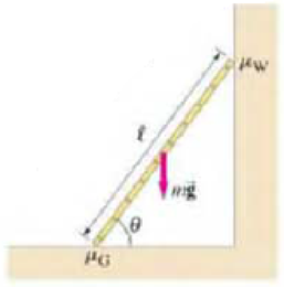
A uniform ladder of mass m and length ℓ leans at an angle θ against a wall, Fig. 12–101. The coefficients of static friction between ladder-ground and ladder-wall are μG and μW, respectively. The ladder will be on the verge of slipping when both the static friction forces due to the ground and due to the wall lake on their maximum values. (a) Show that the ladder will be stable if θ ≥ θmin, where the minimum angle θmin is given by
(b) “Leaning ladder problems” are often analyzed under the seemingly unrealistic assumption that the wall is frictionless (see Example 12–6). You wish to investigate the magnitude of error introduced by modeling the wall as frictionless, if in reality it is frictional. Using the relation found in part (a), calculate the true value of θmin for a frictional wall, taking μG = μW = 0.40. Then, determine the approximate value of θmin for the “friction-less wall” model by taking μG = 0.40 and μW = 0. Finally, determine the percent deviation of the approximate value of θmin from its true value.
FIGURE 12–101 Problem 95.
Want to see the full answer?
Check out a sample textbook solution
Chapter 12 Solutions
Pearson eText -- Physics for Scientists and Engineers with Modern Physics -- Instant Access (Pearson+)
Additional Science Textbook Solutions
Chemistry: Structure and Properties (2nd Edition)
Anatomy & Physiology (6th Edition)
Organic Chemistry (8th Edition)
Human Physiology: An Integrated Approach (8th Edition)
Physics for Scientists and Engineers: A Strategic Approach, Vol. 1 (Chs 1-21) (4th Edition)
Human Anatomy & Physiology (2nd Edition)


- A 0.850-m-long metal bar is pulled to the right at a steady 5.0 m/s perpendicular to a uniform, 0.650-T magnetic field. The bar rides on parallel metal rails connected through a 25-Ω, resistor (Figure 1), so the apparatus makes a complete circuit. Ignore the resistance of the bar and the rails. Please explain how to find the direction of the induced current.arrow_forwardFor each of the actions depicted, determine the direction (right, left, or zero) of the current induced to flow through the resistor in the circuit containing the secondary coil. The coils are wrapped around a plastic core. Immediately after the switch is closed, as shown in the figure, (Figure 1) in which direction does the current flow through the resistor? If the switch is then opened, as shown in the figure, in which direction does the current flow through the resistor? I have the answers to the question, but would like to understand the logic behind the answers. Please show steps.arrow_forwardWhen violet light of wavelength 415 nm falls on a single slit, it creates a central diffraction peak that is 8.60 cm wide on a screen that is 2.80 m away. Part A How wide is the slit? ΟΙ ΑΣΦ ? D= 2.7.10-8 Submit Previous Answers Request Answer × Incorrect; Try Again; 8 attempts remaining marrow_forward
- Two complex values are z1=8 + 8i, z2=15 + 7 i. z1∗ and z2∗ are the complex conjugate values. Any complex value can be expessed in the form of a+bi=reiθ. Find θ for (z1-z∗2)/z1+z2∗. Find r and θ for (z1−z2∗)z1z2∗ Please show all stepsarrow_forwardCalculate the center of mass of the hollow cone shown below. Clearly specify the origin and the coordinate system you are using. Z r Y h Xarrow_forward12. If all three collisions in the figure below are totally inelastic, which will cause more damage? (think about which collision has a larger amount of kinetic energy dissipated/lost to the environment? I m II III A. I B. II C. III m m v brick wall ע ע 0.5v 2v 0.5m D. I and II E. II and III F. I and III G. I, II and III (all of them) 2marrow_forward
- 11. If all three collisions in the figure below are totally inelastic, which brings the car of mass (m) on the left to a halt? I m II III m m ע ע ע brick wall 0.5v 2m 2v 0.5m A. I B. II C. III D. I and II E. II and III F. I and III G. I, II and III (all of them)arrow_forwardHow can you tell which vowel is being produced here ( “ee,” “ah,” or “oo”)? Also, how would you be able to tell for the other vowels?arrow_forwardYou want to fabricate a soft microfluidic chip like the one below. How would you go about fabricating this chip knowing that you are targeting a channel with a square cross-sectional profile of 200 μm by 200 μm. What materials and steps would you use and why? Disregard the process to form the inlet and outlet. Square Cross Sectionarrow_forward
 Physics for Scientists and Engineers: Foundations...PhysicsISBN:9781133939146Author:Katz, Debora M.Publisher:Cengage Learning
 University Physics Volume 1PhysicsISBN:9781938168277Author:William Moebs, Samuel J. Ling, Jeff SannyPublisher:OpenStax - Rice University
 Glencoe Physics: Principles and Problems, Student...PhysicsISBN:9780078807213Author:Paul W. ZitzewitzPublisher:Glencoe/McGraw-Hill
 Physics for Scientists and EngineersPhysicsISBN:9781337553278Author:Raymond A. Serway, John W. JewettPublisher:Cengage Learning
 Physics for Scientists and Engineers with Modern ...PhysicsISBN:9781337553292Author:Raymond A. Serway, John W. JewettPublisher:Cengage Learning
 Principles of Physics: A Calculus-Based TextPhysicsISBN:9781133104261Author:Raymond A. Serway, John W. JewettPublisher:Cengage Learning