
Find the approximate axial forces, shears, and moments for the all members of the frames using cantilever method.
Explanation of Solution
Given information:
The axial force acting at point M (HM) is 7.5 k.
The axial force acting at point I (HI) is 15 k.
The axial force acting at point E (HE) is 15 k.
The vertical distance of the member JM and KL (L1) is 16 ft.
The vertical distance of the member EI, FJ, GK, and HL (L2) is 16 ft.
The vertical distance of the member AE, BF, CG, and DH (L3) is 16 ft.
The horizontal distance of the members AB, EF, and IJ (l1) is 30 ft.
The horizontal distance of the members BC, FG, and JK (l2) is 20 ft.
The horizontal distance of the members CD, GH, and KL (l3) is 30 ft.
Take the counterclockwise moment is positive and clockwise moment is negative.
The axial force in horizontal direction, towards right is positive and towards left side is negative.
The axial force in vertical direction, towards upward is positive and towards downward is negative.
Calculation:
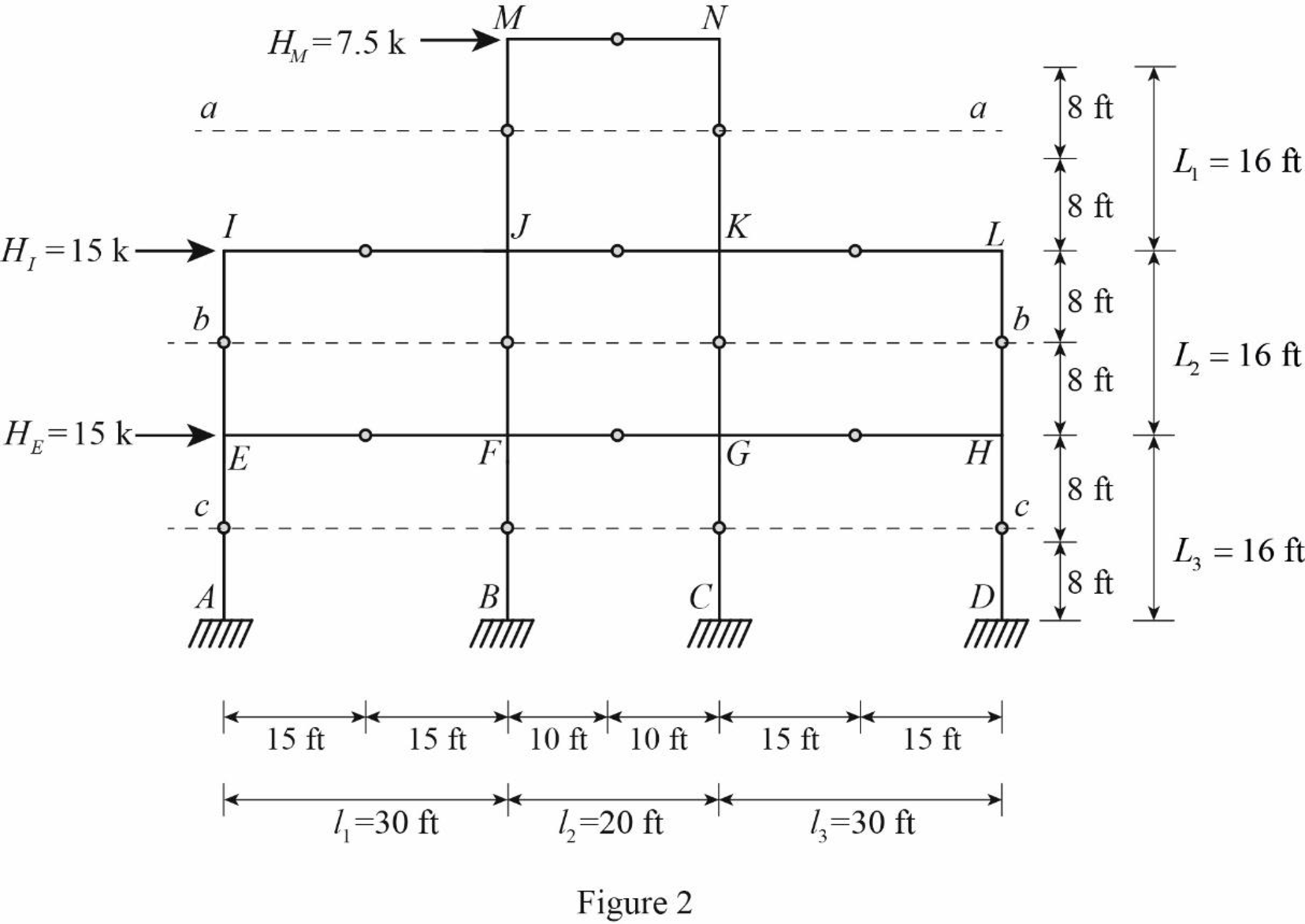
Insert the internal hinges at the midpoints of all the members of the given frame to obtain the simplified frame for approximate analysis.
Draw the simplified frame as in Figure (1).

For the calculation of column axial forces of story of the frame, pass an imaginary section aa through the internal hinges at the midheights of columns JM and KN, pass an imaginary section bb through the internal hinges at the midheights of columns EI, FJ, GK, and HL, and pass an imaginary section cc through the internal hinges at the midheights of columns AE, BF, CG, and DH.
Draw the free body diagram of the frame portion with the passed imaginary lines as in Figure (2).
Column axial forces:
Above section aa:
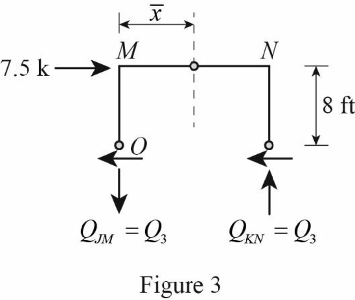
Draw the free body diagram of the frame portion above the section aa as in Figure (3).
Determine the location of the centroid from support A using the relation.
ˉx=∑Ax∑A=∑Ax1+Ax2+Ax3+Ax44A (1)
Here, A is the area of the column sections, x1 is the initial distance, x2 is the distance for the support B from support A, x3 is the distance for the support C from support A, and x4 is the distance for the support D from support A.
Substitute 0 ft for x1, 30 ft for x2, 50 ft for x3, and 80 ft for x4 in Equation (1).
ˉx=A(0)+A(30)+A(50)+A(80)4A=40 ft
The location of the centroid from the column member JM is 10 ft.
The given lateral load is acting on the frame to the right, therefore the axial force in column JM located to the left of the centroid, must be tensile whereas the axial force in column KN placed to the right of the centroid, must be compressive.
Determine the axial force in the column members JM and KN using equilibrium conditions.
Take moment about point O.
∑MO=0Q3×l2−HM×L12=0
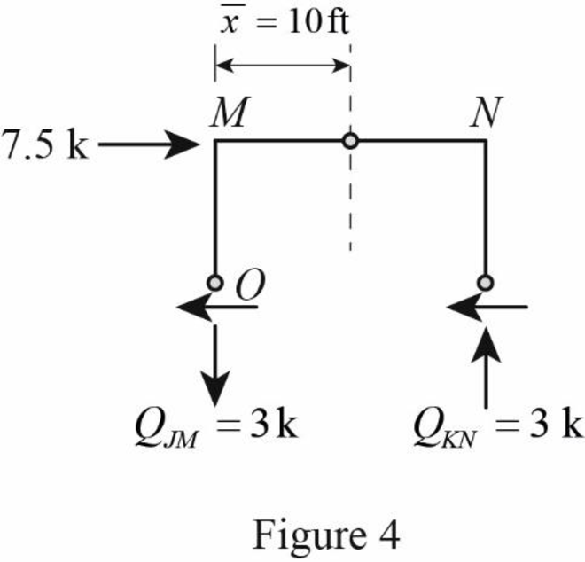
Substitute 20 ft for l2, 20 k for HM, and 16 ft for L1.
Q3×20−7.5×162=020Q3=60Q3=6020Q3=3 k
The axial force in the column members JM and KN is QJM=3 k(↓) and QKN=3 k(↑).
Draw the free body diagram of the frame portion above the section aa with the axial forces in the column members as in Figure (4).
Draw the free body diagram of the frame portion above the section bb as in Figure (5).
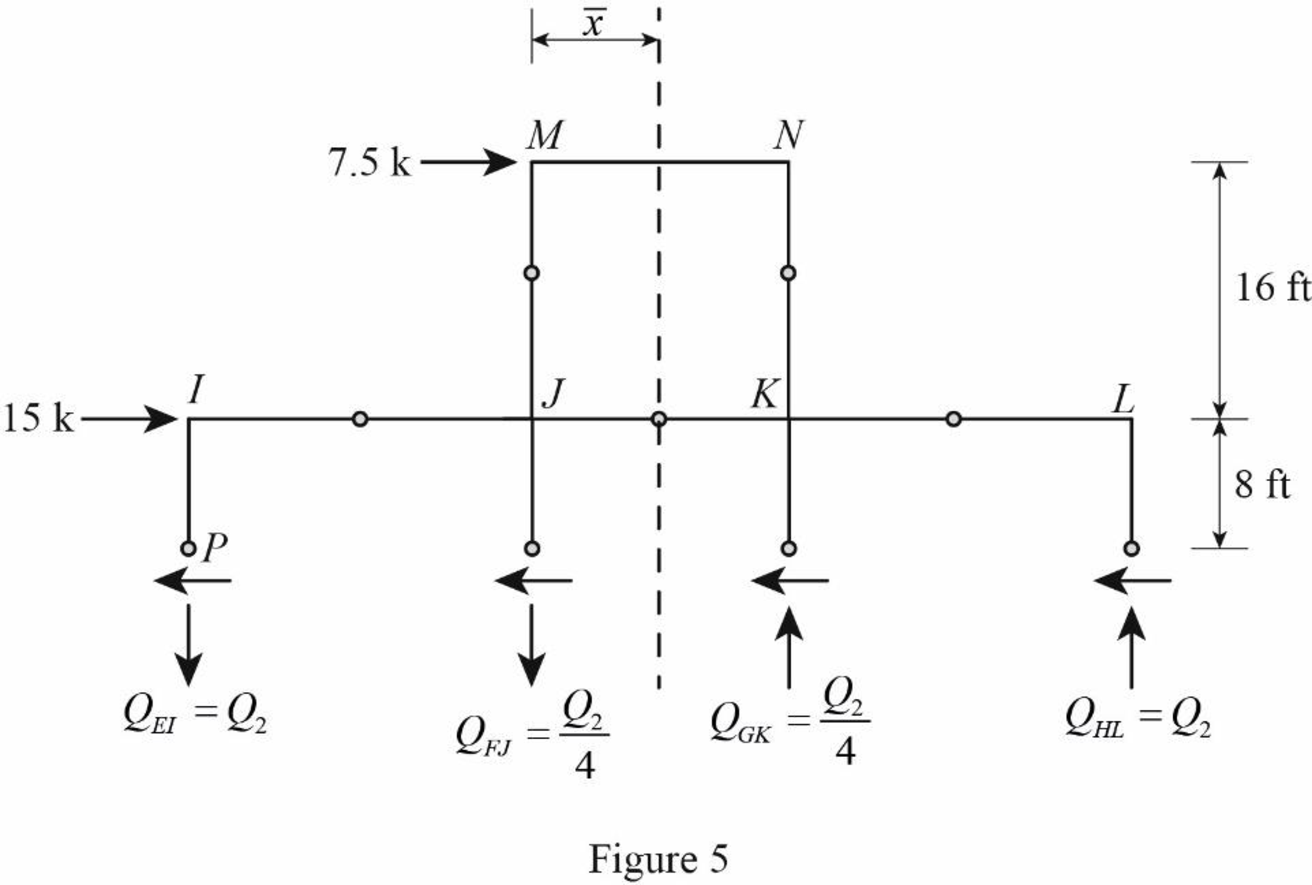
Consider the axial forces in the columns are to be linearly proportional to their distances from centroid.
The given lateral load is acting on the frame to the right, therefore the axial force in column EI and FJ located to the left of the centroid, must be tensile whereas the axial force in column GK and HL placed to the right of the centroid, must be compressive.
Refer Figure (5).
Determine the relationship in column axial force between the member EI and FJ using the relation.
QFJ=ˉx−l1ˉxQEI
Substitute 40 ft for ˉx and 30 ft for l1.
QFJ=40−3040QEI=1040QEI=QEI4
Determine the relationship in column axial force between the member EI and GK using the relation.
QGK=(l1+l2)−ˉxˉxQEI
Substitute 30 ft for l1, 20 ft for l2, and 40 ft for ˉx.
QGK=(30+20)−4040QEI=1040QEI=QEI4
Determine the axial force in the column members EI, FJ, GK, and HL using equilibrium conditions.
Take moment about point P.
∑MP=0QHL×(l1+l2+l3)+QGK×(l1+l2)−QFJ×l1−HM×(L1+L22)−HI×L22=0
Substitute QEI for QHL, 30 ft for l1, 20 ft for l2, 30 ft for l3, QEI4 for QGK, QEI4 for QFJ, 7.5 k for HM, 16 ft for L1, 15 k for HI, and 16 ft for L2.
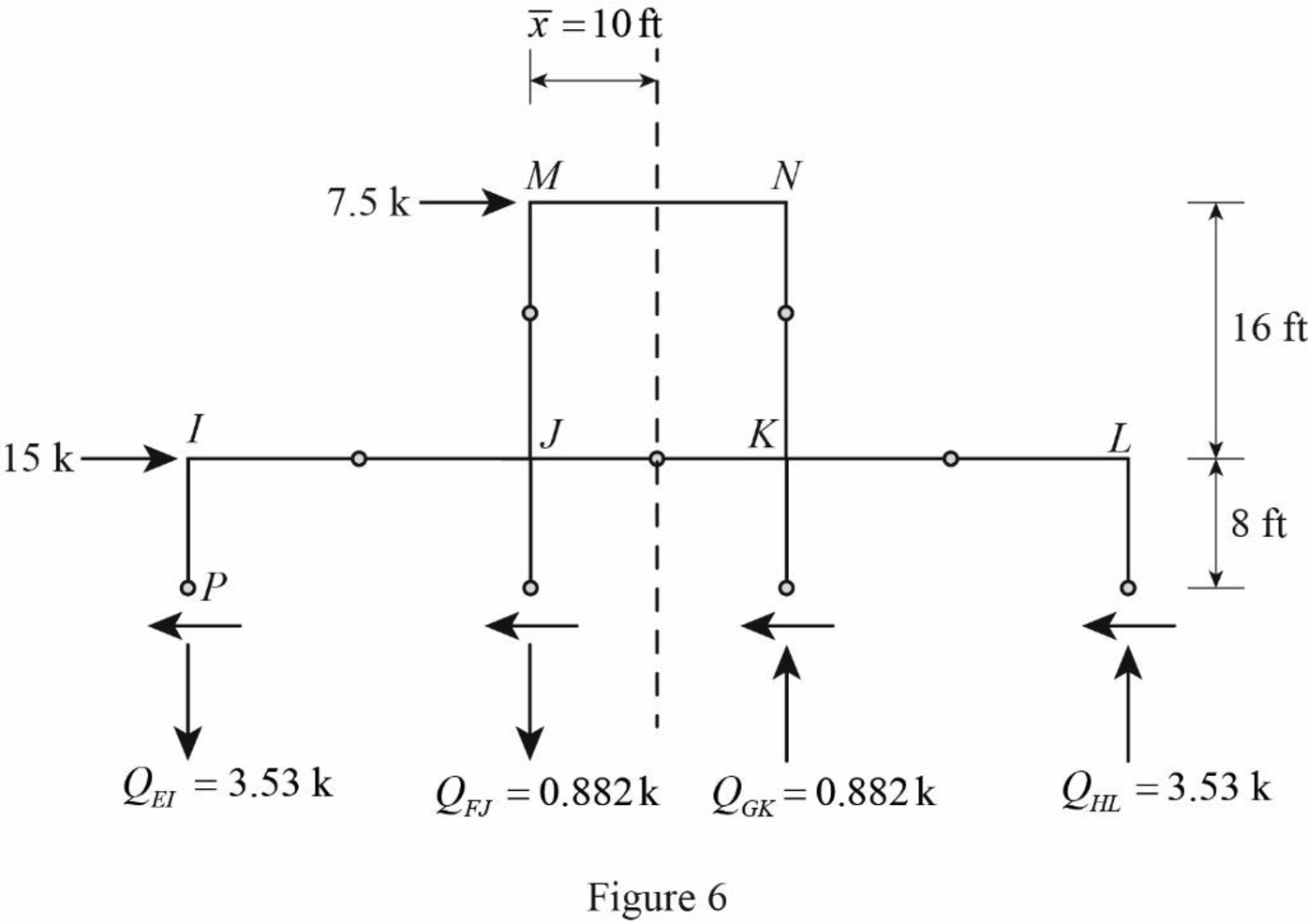
QEI×(30+20+30)+14QEI×(20+30)−14QEI×30−7.5×(16+162)−15×162=080QEI+504QEI−304QEI=300QEI=30085QEI=3.53 k
Determine the axial force in the column members FJ.
QFJ=14QEI
Substitute 3.53 k for QEI.
QFJ=14×3.53=0.882 k(↓)
Determine the axial force in the column members GK.
QGK=14QEI
Substitute 3.53 k for QEI.
QGK=14×3.53=0.882 k(↑)
Determine the axial force in the column members HL.
QHL=QEI
Substitute 3.53 k for QEI.
QHL=3.53 k(↑)
Draw the free body diagram of the frame portion above the section bb with the axial forces in the column members as in Figure (6).
Draw the free body diagram of the frame portion above the section cc as in Figure (7).
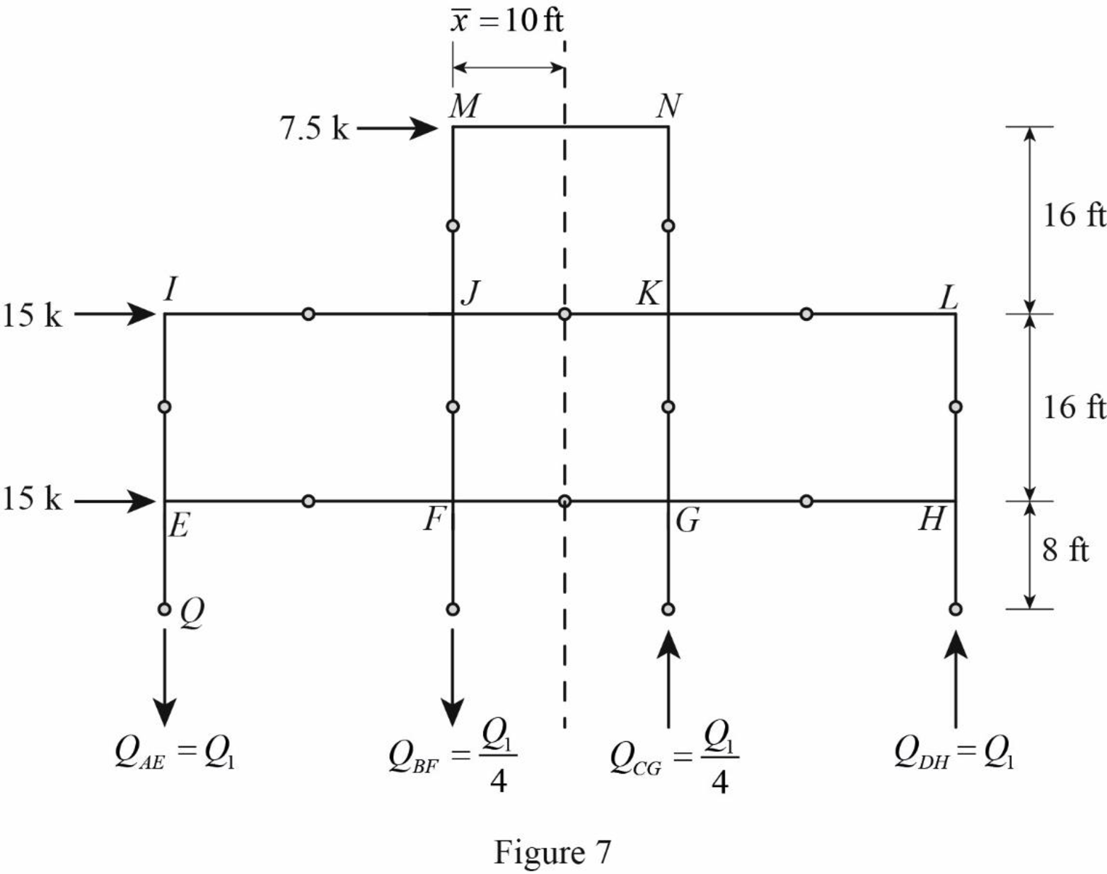
The given lateral load is acting on the frame to the right, therefore the axial force in column AE and BF located to the left of the centroid, must be tensile, whereas the axial force in column CG and DH placed to the right of the centroid, must be compressive.
Determine the relationship in column axial force between the member AE and BF using the relation.
QBF=ˉx−l1ˉxQAE
Substitute 40 ft for ˉx and 30 ft for l1.
QBF=40−3040QAE=1040QAE=QAE4
Determine the relationship in column axial force between the member AE and CG using the relation.
QCG=(l1+l2)−ˉxˉxQAE
Substitute 30 ft for l1, 20 ft for l2, and 40 ft for ˉx.
QCG=(30+20)−4040QAE=1040QAE=QAE4
Determine the axial force in the column members AE, BF, CG, and DH using equilibrium conditions.
Take moment about point Q.
∑MQ=0{QDH×(l1+l2+l3)+QCG×(l1+l2)−QBF×l1−HM×(L1+L2+L32)−HI×(L2+L32)−HE×L32}=0
Substitute QAE for QDH, 30 ft for l1, 20 ft for l2, 30 ft for l3, QAE4 for QCG, QAE4 for QBF, 7.5 k for HM, 16 ft for L1, 16 ft for L2, 16 ft for L3, 15 k for HI, and 15 k for HE.
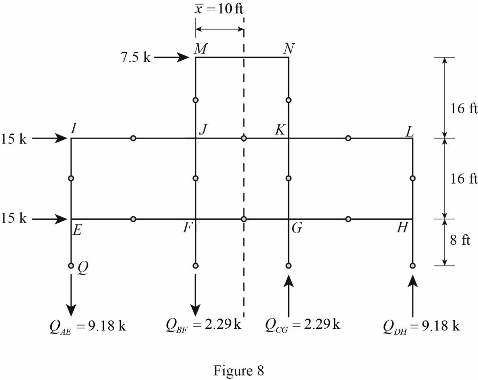
{QAE×(30+20+30)+14QAE×(20+30)−14QAE×30−7.5×(16+16+162)−15×(16+162)−15×162}=080QAE+504QAE−304QAE=780QAE=78085QAE=9.18 k(↓)
Determine the axial force in the column members BF.
QBF=14QAE
Substitute 9.18 k for QAE.
QBF=14×9.18=2.29 k(↓)
Determine the axial force in the column members CG.
QCG=14QAE
Substitute 9.18 k for QAE.
QCG=14×9.18=2.29 k(↑)
Determine the axial force in the column members DH.
QDH=QAE
Substitute 2.29 k for QAE.
QDH=2.29 k(↑)
Draw the free body diagram of the frame portion above the section bb with the axial forces in the column members as in Figure (8).
Girder shear and moments:
Consider girder MN.
Determine the shear at upper left end joint M using equilibrium equation.
∑FY=0SMN−QJM=0
Substitute 3 k for QJM.
SMN+3=0SMN=−3 kSMN=3 k(↓)
Determine the shear at upper right end joint N using equilibrium equation.
∑FY=0−SMN+SNM=0
Substitute 3 k for SNM.
−3+SNM=0SNM=3 k(↑)
Determine the moment at left end of the girder MN using equilibrium equations.
MMN=−SMN×l22
Substitute 3 k for SMN and 20 ft for l2.
MMN=−3×202=30 k-ft(Clockwise)
Determine the moment at right end of the girder NM using equilibrium equations.
Take moment about point M.
∑MM=0−MMN+SNM×l2+MNM=0
Substitute 30 k-ft for MMN, 3 k for SNM, and 20 ft for l2.
−30+3×20+MNM=0MNM=−30 k-ftMNM=30 k-ft(Clockwise)
Consider girder IJ.
Determine the shear at upper left end joint I using equilibrium equation.
∑FY=0SIJ+QIE=0
Substitute 3.53 k for QIE.
SIJ+3.53=0SIJ=−3.53 kSIJ=3.53 k(↓)
Determine the shear at upper right end joint J using equilibrium equation.
∑FY=0−SIJ+SJI=0
Substitute 3.53 k for SIJ.
−3.53+SJI=0SJI=3.53 k(↑)
Determine the moment at left end of the girder IJ using equilibrium equations.
MIJ=−SIJ×l12
Substitute 3.53 k for SIJ and 30 ft for l1.
MIJ=−3.53×302≈53 k-ft(Clockwise)
Determine the moment at right end of the girder IJ using equilibrium equations.
Take moment about point I.
∑MI=0−MIJ+SJI×l1+MJI=0
Substitute 53 k-ft for MIJ, 3.53 k for SJI, and 30 ft for l1.
−53+3.53×30+MJI=0MJI=−53 k-ftMJI=53 k-ft(Clockwise)
Consider girder JK.
Determine the shear at left end joint J using equilibrium equation.
∑FY=0SJI+SJK+QJF−QJM=0
Substitute 3.53 k for SJI, 0.882 k for QJF, and 3 k for QJM.
3.53+SJK+0.882−3=0SJK=−1.41 kSJK=1.41 k(↓)
Determine the shear at right end joint K using equilibrium equation.
∑FY=0−SJK+SKJ=0
Substitute 1.41 k for SJK.
−1.41+SJK=0SJK=1.41 k(↑)
Determine the moment at left end of the girder JK using equilibrium equations.
MJK=−SJK×l22
Substitute 1.41 k for SJK and 20 ft for l2.
MJK=−1.41×202=−14.1 k-ft=14.1 k-ft(Clockwise)
Determine the moment at right end of the girder JK using equilibrium equations.
Take moment about point J.
∑MJ=0−MJK+SKJ×l2+MKJ=0
Substitute 14.1 k-ft for MJK, 1.41 k for SKJ, and 20 ft for l2.
−14.1+1.41×20+MKJ=0MKJ=−14.1 k-ftMKJ=14.1 k-ft(Clockwise)
Consider girder KL.
Determine the shear at left end joint K using equilibrium equation.
∑FY=0SKJ+SKL−QKG+QKN=0
Substitute 1.41 k for SKJ, 0.882 k for QKG, and 3 k for QKN.
1.41+SKL−0.882+3=0SKL=−3.53 kSKL=3.53 k(↓)
Determine the shear at right end joint L using equilibrium equation.
∑FY=0−SKL+SLK=0
Substitute 3.53 k for SKL.
−3.53+SKL=0SKL=3.53 k(↑)
Determine the moment at left end of the girder KL using equilibrium equations.
MKL=−SKL×l32
Substitute 3.53 k for SKL and 30 ft for l3.
MKL=−3.53×302≈−53 k-ft=53 k-ft(Clockwise)
Determine the moment at right end of the girder JK using equilibrium equations.
Take moment about point K.
∑MK=0−MKL+SLK×l3+MLK=0
Substitute 53 k-ft for MJK, 3.53 k for SLK, and 30 ft for l3.
−53+3.53×30+MLK=0MLK=−53 k-ftMLK=53 k-ft(Clockwise)
Consider girder EF.
Determine the shear at left end joint E using equilibrium equation.
∑FY=0SEF−QEI+QEA=0
Substitute 3.53 k for QEI and 9.18 k for QEA.
SEF−3.53+9.18=0SEF=−5.65 kSEF=5.65 k(↓)
Determine the shear at right end joint F using equilibrium equation.
∑FY=0−SEF+SFE=0
Substitute 5.65 k for SEF.
−5.65+SFE=0SFE=5.65 k(↑)
Determine the moment at left end of the girder EF using equilibrium equations.
MEF=−SEF×l12
Substitute 5.65 k for SEF and 30 ft for l1.
MEF=−5.65×302=−84.75 k-ft=84.75 k-ft(Clockwise)
Determine the moment at right end of the girder EF using equilibrium equations.
Take moment about point E.
∑ME=0−MEF+SFE×l1+MFE=0
Substitute 84.75 k-ft for MEF, 5.65 k for SFE, and 30 ft for l1.
−84.75+5.65×30+MFE=0MFE=−84.75 k-ftMFE=84.75 k-ft(Clockwise)
Consider girder FG.
Determine the shear at left end joint F using equilibrium equation.
∑FY=0SFE+SFG−QFJ+QFB=0
Substitute 5.65 k for SFE, 0.882 k for QFJ, and 2.29 k for QFB.
5.65+SFG−0.882+2.29=0SFG=−7.06 kSFG=7.06 k(↓)
Determine the shear at right end joint G using equilibrium equation.
∑FY=0−SFG+SGF=0
Substitute 7.06 k for SFG.
−7.06+SGF=0SGF=7.06 k(↑)
Determine the moment at left end of the girder FG using equilibrium equations.
MFG=−SFG×l22
Substitute 7.06 k for SFG and 20 ft for l2.
MFG=−7.06×202=−70.6 k-ft=70.6 k-ft(Clockwise)
Determine the moment at right end of the girder FG using equilibrium equations.
Take moment about point F.
∑MF=0−MFG+SGF×l2+MGF=0
Substitute 70.6 k-ft for MFG, 7.06 k for SGF, and 20 ft for l2.
−70.6+7.06×20+MGF=0MGF=−70.6 k-ftMGF=70.6 k-ft(Clockwise)
Consider girder GH.
Determine the shear at left end joint G using equilibrium equation.
∑FY=0SGH+SGF+QGK−QGC=0
Substitute 7.06 k for SGF, 0.882 k for QGK, and 2.29 k for QGC.
SGH+7.06+0.882−2.29=0SGH=−5.65 kSGH=5.65 k(↓)
Determine the shear at right end joint H using equilibrium equation.
∑FY=0−SGH+SHG=0
Substitute 5.65 k for SGH.
−5.65+SHG=0SHG=5.65 k(↑)
Determine the moment at left end of the girder GH using equilibrium equations.
MGH=−SGH×l32
Substitute 5.65 k for SGH and 30 ft for l3.
MGH=−5.65×302=−84.75 k-ft=84.75 k-ft(Clockwise)
Determine the moment at right end of the girder GH using equilibrium equations.
Take moment about point G.
∑MG=0−MGH+SHG×l3+MHG=0
Substitute 84.75 k-ft for MGH, 5.65 k for SHG, and 30 ft for l3.
−84.75+5.65×30+MHG=0MHG=−84.75 k-ftMHG=84.75 k-ft(Clockwise)
Column moments and shears:
Column moment for member JM and KN:
Determine the moment at the column member JM using moment equilibrium of joints.
Apply the moment equilibrium of joints at M.
∑M=0MMJ−MMN=0
Substitute 30 k-ft for MMN.
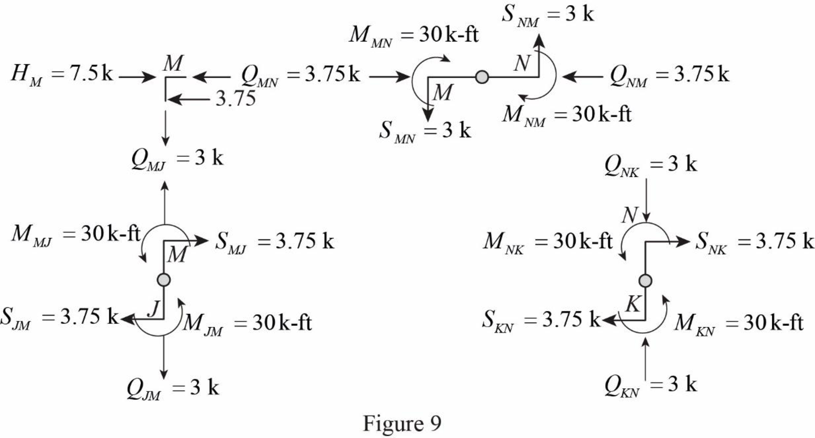
MMJ−30=0MMJ=30 k-ft(Counterclockwise)
The moment at the column member JM is MJM=MMJ=30 k-ft(Counterclockwise).
Determine the moment at the column member KN using moment equilibrium of joints.
Apply the moment equilibrium of joints at N.
∑M=0MNK−MNM=0
Substitute 30 k-ft for MNM.
MNK−30=0MNK=30 k-ft(Counterclockwise)
The moment at the column member KN is MKN=MNK=30 k-ft(Counterclockwise).
Column shear for member JM and KN:
Determine the shear at the end M in the column member JM using the relation.
SMJ=MMJL12
Substitute 30 k-ft for MMJ and 16 ft for L1.
SMJ=30162=3.75 k(→)
The shear at the column member MJ must act towards right, so that it can produce Clockwise moment to balance the counterclockwise moment at joint M.
Determine the shear at the end of the column J using equilibrium conditions.
∑FX=0SMJ+SJM=0
Substitute 3.75 k for SMJ.
3.75+SJM=0SJM=−3.75 kSJM=3.75 k(←)
Determine the shear at the end N in the column member KN using the relation.
SNK=MNKL12
Substitute 30 k-ft for MNK and 16 ft for L1.
SNK=30162=3.75 k(→)
The shear at the column member NK must act towards right, so that it can produce Clockwise moment to balance the counterclockwise moment at joint N.
Determine the shear at the end of the column K using equilibrium conditions.
∑FX=0SNK+SKN=0
Substitute 3.75 k for SNK.
3.75+SKN=0SKN=−3.75 kSKN=3.75 k(←)
Column moment for member EI, FJ, GK, and HL:
Determine the moment at the column member EI using moment equilibrium of joints.
Apply the moment equilibrium of joints at I.
∑M=0MIE−MIJ=0
Substitute 53 k-ft for MIJ.
MIE−53=0MIE=53 k-ft(Counterclockwise)
The moment at the column member EI is MEI=MIE=53 k-ft(Counterclockwise).
Determine the moment at the column member FJ.
Apply the moment equilibrium of joints at J.
∑M=0−MJI−MJK+MJF+MJM=0
Substitute 53 k-ft for MJI, 14.1 k-ft for MJK, and 30 k-ft for MJM.
−53−14.1+MJF+30=0MJF=37.1 k-ft(Counterclockwise)
The moment at the column member FJ is MJF=MFJ=37.1 k-ft(Counterclockwise).
Determine the moment at the column member GK.
Apply the moment equilibrium of joints at K.
∑M=0−MKJ−MKL+MKG+MKN=0
Substitute 14.1 k-ft for MKJ, 53 k-ft for MKL, and 30 k-ft for MKN.
−14.1−53+MKG+30=0MKG=37.1 k-ft(Counterclockwise)
The moment at the column member GK is MKG=MGK=37.1 k-ft(Counterclockwise).
Determine the moment at the column member HL using moment equilibrium of joints.
Apply the moment equilibrium of joints at L.
∑M=0−MLK+MLH=0
Substitute 53 k-ft for MLK.
−53+MLH=0MLH=53 k-ft(Counterclockwise)
The moment at the column member IF is MLH=MHL=53 k-ft(Counterclockwise).
Column shear for member EI, FJ, GK, and HL:
Determine the shear at the end I in the column member EI using the relation.
SIE=MIEL22
Substitute 53 k-ft for MIE and 16 ft for L2.
SIE=53162=6.62 k(→)
The shear at the column member IE must act towards right, so that it can produce Clockwise moment to balance the counterclockwise moment at joint I.
Determine the shear at the end of the column E using equilibrium conditions.
∑FX=0SIE+SEI=0
Substitute 6.62 k for SIE.
6.62+SEI=0SEI=−6.62 kSEI=6.62 k(←)
Determine the shear at the end J in the column member FJ using the relation.
SJF=MJFL22
Substitute 37.1 k-ft for MEH and 16 ft for L2.
SJF=37.1162=4.64 k(→)
The shear at the column member JF must act towards right, so that it can produce Clockwise moment to balance the counterclockwise moment at joint J.
Determine the shear at the end of the column F using equilibrium conditions.
∑FX=0SJF+SFJ=0
Substitute 4.64 k for SJF.
4.64+SFJ=0SFJ=−4.64 kSFJ=4.64 k(←)
Determine the shear at the end K in the column member GK using the relation.
SKG=MKGL12
Substitute 37.1 k-ft for MKG and 16 ft for L2.
SKG=37.1162=4.64 k(→)
The shear at the column member KG must act towards right, so that it can produce Clockwise moment to balance the counterclockwise moment at joint K.
Determine the shear at the end of the column G using equilibrium conditions.
∑FX=0SKG+SGK=0
Substitute 4.64 k for SKG.
4.64+SGK=0SGK=−4.64 kSGK=4.64 k(←)
Determine the shear at the end L in the column member HL using the relation.
SLH=MLHL12
Substitute 53 k-ft for MLH and 16 ft for L2.
SLH=53162=6.62 k(→)
The shear at the column member LH must act towards right, so that it can produce Clockwise moment to balance the counterclockwise moment at joint L.
Determine the shear at the end of the column H using equilibrium conditions.
∑FX=0SLH+SHL=0
Substitute 6.62 k for SLH.
6.62+SHL=0SHL=−6.62 kSHL=6.62 k(←)
Column moment for member AE, BF, CG, and DH:
Determine the moment at the column member AE using moment equilibrium of joints.
Apply the moment equilibrium of joints at E.
∑M=0MEA−MEF+MEI=0
Substitute 84.75 k-ft for MEF and 53 k-ft for MEI.
MEA−84.75+53=0MEA=31.75 k-ft(Counterclockwise)
The moment at the column member AE is MAE=MEA=31.75 k-ft(Counterclockwise).
Determine the moment at the column member BF.
Apply the moment equilibrium of joints at F.
∑M=0MFB−MFE−MFG+MFJ=0
Substitute 84.75 k-ft for MFE, 70.6 k-ft for MFG, and 37.1 k-ft for MFJ.
MFB−84.75−70.6+37.1=0MFB=118.25 k-ft(Counterlockwise)
The moment at the column member BF is MFB=MBF=118.25 k-ft(Counterlockwise).
Determine the moment at the column member CG using moment equilibrium of joints.
Apply the moment equilibrium of joints at C.
∑M=0MGC−MGF−MGH+MGK=0
Substitute 70.6 k-ft for MGF, 84.75 k-ft for MGH, and 37.1 k-ft for MGK.
MGC−70.6−84.75+37.1=0MGC=118.25 k-ft(Counterlockwise)
The moment at the column member CG is MCG=MGC=118.25 k-ft(Counterlockwise).
Determine the moment at the column member DH using moment equilibrium of joints.
Apply the moment equilibrium of joints at H.
∑M=0MHD−MHG+MHL=0
Substitute 84.75 k-ft for MHG and 53 k-ft for MHL.
MHD−84.75+53=0MHD=31.75 k-ft(Counterclockwise)
The moment at the column member DH is MDH=MHD=31.75 k-ft(Counterclockwise).
Column shear for member AE, BF, CG, and DH:
Determine the shear at the end E in the column member AE using the relation.
SEA=MEAL32
Substitute 31.75 k-ft for MEA and 16 ft for L3.
SEA=31.75162=3.97 k(→)
The shear at the column member EA must act towards right, so that it can produce Clockwise moment to balance the counterclockwise moment at joint E.
Determine the shear at the lower end of the column A using equilibrium conditions.
∑FX=0SEA+SAE=0
Substitute 3.97 k for SEA.
3.97+SAE=0SAE=−3.97 kSAE=3.97 k(←)
Determine the shear at the end F in the column member BF using the relation.
SFB=MFBL22
Substitute 118.25 k-ft for MEB and 16 ft for L3.
SFB=118.25162=14.78 k(→)
The shear at the column memer FB must act towards right, so that it can produce Clockwise moment to balance the counterclockwise moment at joint F.
Determine the shear at the lower end of the column B using equilibrium conditions.
∑FX=0SFB+SBF=0
Substitute 14.78 k for SEB.
14.78+SBF=0SBF=−14.78 kSBF=14.78 k(←)
Determine the shear at the end G in the column member CG using the relation.
SGC=MGCL32
Substitute 118.25 k-ft for MGC and 16 ft for L3.
SGC=118.25162=14.78 k(→)
The shear at the column member GC must act towards right, so that it can produce counterclockwise moment to balance the clockwise moment at joint G.
Determine the shear at the lower end of the column C using equilibrium conditions.
∑FX=0SGC+SCG=0
Substitute 14.78 k for SGC.
14.78+SCG=0SCG=−14.78 kSCG=14.78 k(←)
Determine the shear at the end H in the column member DH using the relation.
SHD=MHDL32
Substitute 31.75 k-ft for MHD and 6 m for L3.
SHD=31.75162=3.97 k(→)
The shear at the column member HD must act towards right, so that it can produce Clockwise moment to balance the counterclockwise moment at joint H.
Determine the shear at the lower end of the column A using equilibrium conditions.
∑FX=0SHD+SDH=0
Substitute 3.97 k for SHD.
3.97+SDH=0SDH=−3.97 kSDH=3.97 k(←)
Draw the free body diagram of frame with the column moments and shears for the portion EIJ as in Figure (9).
Girder axial forces:
Girder MN.
Determine the girder end action at the upper left end joint M using the equilibrium condition.
Apply equilibrium condition at left end joint M.
∑FX=0QMN−SMJ+HM=0
Substitute 3.75 k for SMJ and 7.5 k for HM.
QIJ−3.75+7.5=0QIJ=−3.75 kQIJ=3.75 k(←)
The girder end action at joint M in the girder MN is QMN=3.75 k(→).
Determine the girder end action at the upper right end joint H using the equilibrium condition.
Apply equilibrium condition at end joint M.
∑FX=0QMN+QNM=0
Substitute 3.75 k for QMN.
3.75+QMN=0QMN=−3.75 kQMN=3.75 k(←)
Girder IJ.
Determine the girder end action at the upper left end joint I using the equilibrium condition.
Apply equilibrium condition at left end joint I.
∑FX=0QIJ−SIE+HI=0
Substitute 6.62 k for SIE and 15 k for HI.
QIJ−6.62+15=0QIJ=−8.38 kQIJ=8.38 k(←)
The girder end action at joint I in the girder IJ is QIJ=8.38 k(→).
Determine the girder end action at the upper right end joint H using the equilibrium condition.
Apply equilibrium condition at end joint J.
∑FX=0QIJ+QJI=0
Substitute 8.38 k for QIJ.
8.38+QJI=0QJI=−8.38 kQJI=8.38 k(←)
Girder JK.
Determine the girder end action at the left end joint J for the girder JK using the relation.
∑FX=0−QJI+QJK+SJF−SJM=0
Substitute 8.38 k for QJI, 4.64 k for SJF, and 3.75 k for SJM.
−8.38+QJK+4.64−3.75=0QJK=7.49 k(→)
Determine the girder end action at the right end joint K.
∑FX=0QJK+QKJ=0
Substitute 7.49 k for QJK.
7.49+QKJ=0QKJ=7.49 kQKJ=7.49 k(←)
Girder KL.
Determine the girder end action at the left end joint K for the girder KL using the relation.
∑FX=0−QKJ+QKL+SKG−SKN=0
Substitute 7.49 k for QKJ, 4.64 k for SKG, and 3.75 k for SKN.
−7.49+QKL+4.64−3.75=0QKL=6.62 k(→)
Determine the girder end action at the right end joint L.
∑FX=0QKL+QLK=0
Substitute 6.62 k for QKL.
6.62+QLK=0QLK=−6.62 kQLK=6.62 k(←)
Girder EF.
Apply equilibrium condition at left end joint E.
∑FX=0−QEF−SEA+SEI+HE=0
Substitute 3.97 k for SEA, 6.62 k for SEI, and 15 k for HE.
−QEF−3.97+6.62+15=0QEF=17.65 k(→)
The girder end action at joint E in the girder EF is QEF=17.65 k(→).
Determine the girder end action at the right end joint F using the equilibrium condition.
Apply equilibrium condition at left end joint F.
∑FX=0QEF+QFE=0
Substitute 17.65 k for QEF.
17.65+QFE=0QFE=−17.65 kQFE=17.65 k(←)
Determine the girder end action at the left end joint F for the girder FG using equilibrium condition.
∑FX=0QFG−QFE+SFB−SFJ=0
Substitute 17.65 k for QFE, 14.78 k for SFB, and 4.64 k for SFJ.
QFG−17.65+14.78−4.64=0QFG=7.51 k(→)
Determine the girder end action at the right end joint G.
∑FX=0QFG+QGF=0
Substitute 7.51 k for QFG.
7.51+QGF=0QGF=−7.51 kQGF=7.51 k(←)
Determine the girder end action at the left end joint G for the girder GH using equilibrium condition.
∑FX=0QGH−QGF+SGC−SGK=0
Substitute 7.51 k for QGF, 14.78 k for SGC, and 4.64 k for SGK.
QGH−7.51+14.78−4.64=0QGH=2.63 k(→)
Determine the girder end action at the right end joint H.
∑FX=0QGH+QHG=0
Substitute 2.63 k for QGH.
2.63+QHG=0QHG=−2.63 kQHG=2.63 k(←)
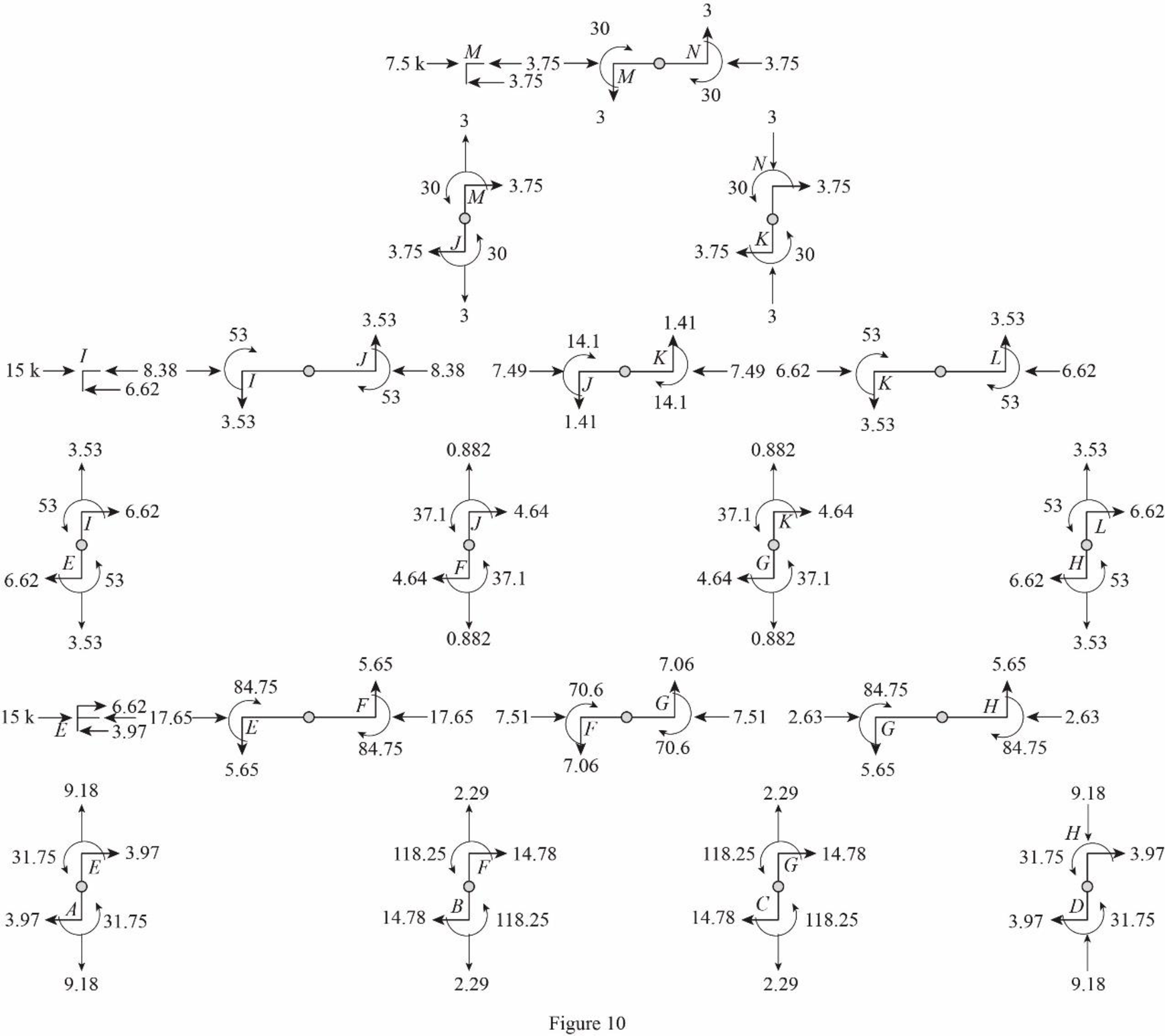
Draw the freebody diagram of the member end forces and moments as in Figure (10).
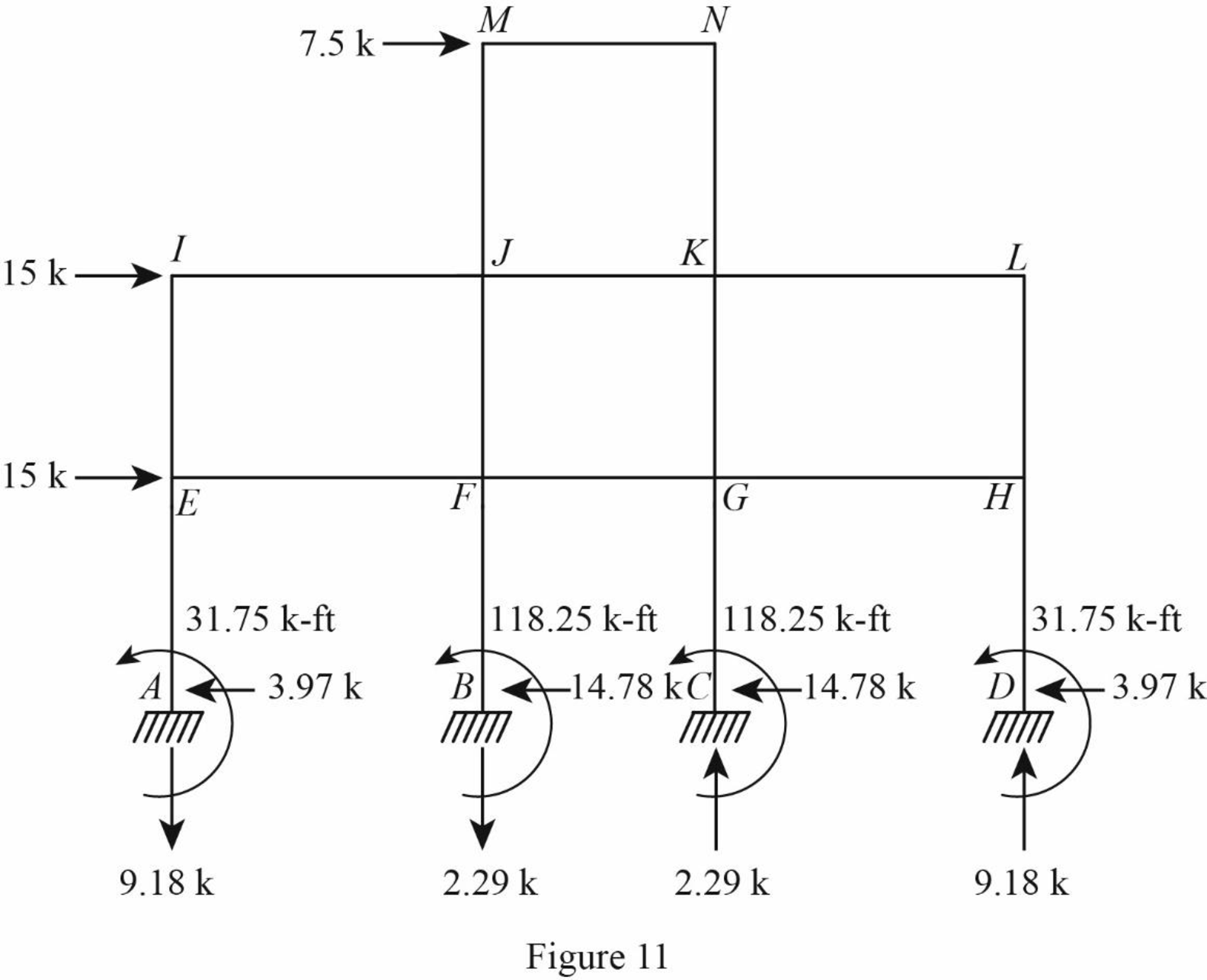
Draw the freebody diagram of the frame with support reactions and moment as in Figure (11).
Want to see more full solutions like this?
Chapter 12 Solutions
Structural Analysis, SI Edition

- Please answer the two questions in detail and as best as you can. Please ensure it is 100% done by human, please do not use AI or chatgpt.arrow_forwardPlease answer the two questions in detail and as best as you can. Please ensure it is 100% done by human, please do not use AI or chatgpt.arrow_forwardPlease provide a handwritten solution to the questionarrow_forward
- kevin.w.wickline@wv.govarrow_forwardWhat is the value of the influence line for the bending moment around B at B for the beam shown? Determine the influence line ordinates at 3-m intervals. Select the reaction at support C to be the redundant. A a. 1.875 kN 6 m b. 0.688 kN c. 2.25 kN > d. 0.313 KN B -12 m- El = constant Carrow_forwardH.W: An activated sludge process operates under the following data: Q=0.21 m³/s, S.- 250 mg/l, S-6.2 mg/l, MLVSS (X) = 3500 mg/1, 0= 10 days Return sludge concentration (X)= 10000 mg/l, Y=0.5, K₁ =0.06 d', volatile super solid represent 80% of SS, Find: 1- Treatment efficiency 2- Reactor volume 3- Qwa (sludge wasted from areation tank) 4- Qur (sludge wasted from recirculation tank) 5- Quantity of sludge wasted/day 6- Recirculated ratio V.X VX Qwa Qwr= Qwr-Xr 0Xarrow_forward
- For the beam shown, where should a uniformly distributed downward live load, wl, be placed to cause the maximum upward reaction at support A? (D, E, and F are the supports, from left to right, to the right of C.) B C a. From A to B and D to E b. From A to D and E to F c. From B to D and E to F ☑ d. From B to C and D to E L Larrow_forwardQuestion 1 1. A solid shaft of 1.55 m is used as a tractor propeller (prop) shaft. The shaft twists through 1.8 while rotating at 900 rpm. The diameter of the shaft is 60 mm and the modulus of rigidity is 85 GPa. Calculate 1.1 The maximum shear stress in the shaft 1.2 The power transmitted by the shaft. 2. The tractor has undergone minor modifications to increase the transmitted power by 20%. The solid shaft is replaced by a lighter hollow shaft of the same material, with a dimeter ratio of 2:1. Calculate the suitable dimeters of the hollow shaft.arrow_forwardUse Area Moment Method of Beam Deflectionsarrow_forward
- Determine rotations at all the nodes of the beam and reactions at the supports. Assume support 1 and 3 are roller and support 2 is pinned, L1=1.25m, L2=3.75m and w=60kN/m. Please show all working and FBD's where relevant.arrow_forwardspecific gravity of the soil is 1.41 percentage of water content by weight at field capacity and wilting point are 15% and 7% respectively calculate the equivalent moisture content as equivalent depth for 1.2m root zone: A. At permanent wilting point B. At field capacity C. For ready available water Ex 4-3: If the crop consumptive use in Ex(4-2) is 18 m³/donum/day,calculate: A. Irrigation interval in days B. Field water duty assuming 40% losses during irrigation C. Amount of added water to irrigate one donum. n: CFc- IWC) * As *D Lg dn - Q.te A date. A d9 Q IWC- 20% FC-271 Qg-40e D=100cm sec area of the field. Ed=65% 1 hectare As 1.3arrow_forward۰۹:۲۵ ZV9 HW2-C.pdf Dept: Civil Eng. Kerbala HW2 3rd Year (C) Ex 4-1: The field capacity and wilting point as depth equivalent of soil are 178mm and 102 mm respectively. PAD-60% Calculate the irrigation interval if the water consumptive use is 4.5 mm/day. Ex 4-2: The specific gravity of the soil is 1.41 percentage of water content by weight at field capacity and wilting point are 15% and 7% respectively. a) calculate the equivalent depth of moisture content for 1.2m root zone and PAD 70% at permanent wilting point, at field capacity and for readily available water b) If the crop consumptive use is 18 m/donum/day, calculate: Irrigation interval in days, field water duty assuming 40% losses during irrigation and amount of added water to irrigate one hectare. Ex4-3: Using Blaney-Criddle formula, calculate the irrigation interval through specific interval of plant growth according to the following data: . Mean air temperature 25 C percentage of day light hour through the month 8.4% Crop…arrow_forward
