
Draw the shear and bending moment diagrams for the girders of given frame.
Explanation of Solution
Given information:
The uniformly distributed load acting along the girder DEF (w) is 30 kN/m.
The horizontal distance of the point AB and BC
The vertical distance of the members AD, BE, and CF
Calculation:
The span length and loads for the two girders of the frame DE and EF are same; therefore the approximate shear and bending moment diagrams for the girders will also be the same.
Consider the girder DE.
Determine the span for the middle portion of the girder using the relation.
Substitute 6 m for L.
Determine the span for the two end portion of the girder using the relation.
Substitute 6 m for L.
Draw the statically determinate girder portion as in Figure (1).
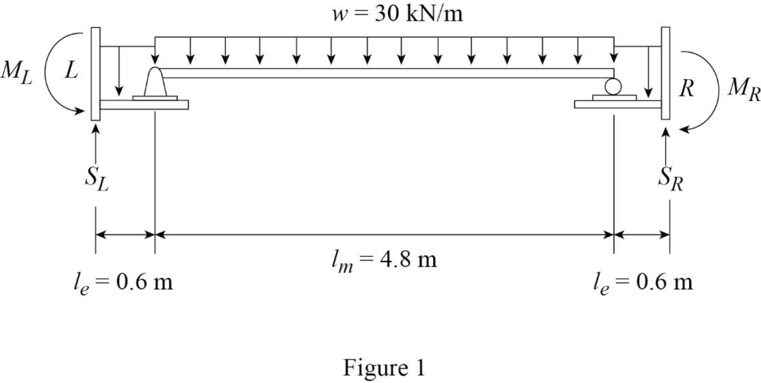
Consider the equilibrium of the simply supported middle portion of the girder.
Determine the vertical reactions at the end portion using the relation.
Substitute 30 kN/m for w and 4.8 m for
Consider the equilibrium conditions of the end portions of the girder.
Consider upward direction is positive and counter clockwise moment is positive.
Determine the support reaction at the left end.
Apply the equations of equilibrium to the left end portion.
Substitute 30 kN/m for w, 0.6 m for
Determine the moment at the left end.
Take moment about left end is equal to zero.
Substitute 30 kN/m for w, 0.6 m for
Consider upward direction is positive and clockwise moment is positive.
Determine the support reaction at the right end.
Apply the equations of equilibrium to the right end portion.
Substitute 30 kN/m for w, 0.6 m for
Determine the moment at the right end.
Take moment about right end is equal to zero.
Substitute 30 kN/m for w, 0.6 m for
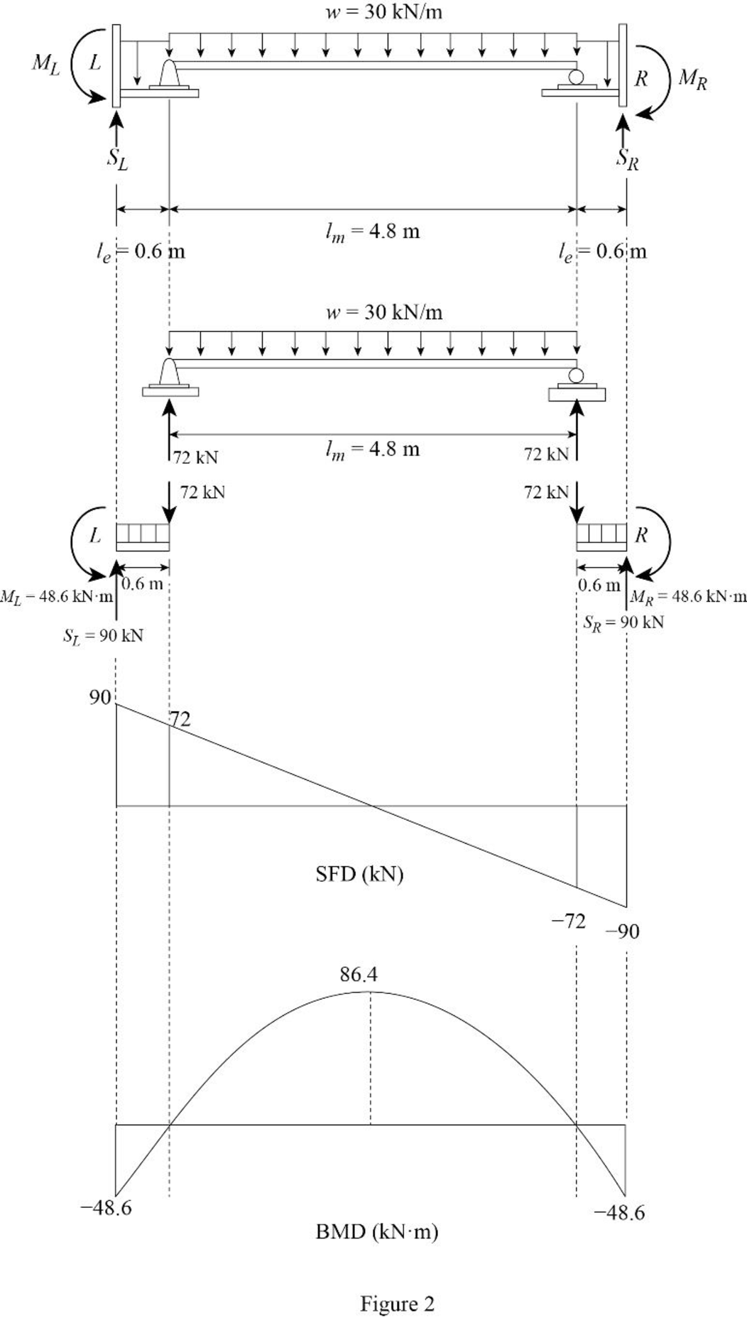
Determine the maximum bending moment at the middle of the girder using the relation.
Substitute 30 kN/m for w and 4.8 m for
Draw the shear force and bending moment diagram as in Figure (2).
Want to see more full solutions like this?
Chapter 12 Solutions
Structural Analysis, SI Edition

- According to the site safety layout what is the biggest potential safety risk? A) PPE Station Located too lose to a heavy equipment zone B) Emergency assemlt point is near the parking lot C)Fire Extingishers are placed every 50 ft. D) Only one site entrance is open for deliveriesarrow_forwardwhich method is most effective for controlling costs and tracking budget performance during a construction project? A)SWOT Analysis B)Root Cause Analysis C)Gantt Chart D) Value Stream Mappingarrow_forward9.44 High-speed passenger trains are streamlined to reduce shear force. The cross section of a passenger car of one such train is shown. For a train 81 m long, estimate the shear force (a) for a speed of 81.1 km/hr and (b) for one of 204 km/hr. What power is required for just the shear force at these speeds? These two power calculations will be answers (c) and (d), respectively. Assume T = 10°C and that the boundary layer is tripped at the front of the train. 10 m Problem 9.44arrow_forward
- A monitoring program for water flow in an unsaturated soil layer includes sensors to measure the volumetric water content and suction up to a depth of 3 m. The soil is a sand whose hydraulic properties are shown in the figures below. Using the drying curves, draw a quantitatively accurate set of vertical profiles of volumetric water content, pressure head, and total hydraulic head versus depth (with a datum at the base of the soil layer and an elevation head that is positive upward) expected for the following cases:A) The volumetric water content (moisture content) is 10% throughout the profile B) The pressure head is -150 cm throughout the profile C) The total hydraulic head is 100 cm throughout the profile (static no-flow case) Also, report the hydraulic gradient for each case. For parts (a) and (b), calculate the flow rates through the profile. For part (c), calculate the depth to the water table.arrow_forward9.16 Two vertical parallel plates are spaced 0.012 ft apart. If the pressure decreases at a rate of 100 psf/ft in the vertical z direction in the fluid between the plates, what is the maximum fluid velocity in the Z direction? The fluid has a viscosity of 10-3 Ibf s/ft² and a specific gravity of 0.80. .arrow_forwardPlease explain steps using software.arrow_forward
- Please explain steps for using softwarearrow_forwardDesign the reinforced masonry beam in the wall shown below. The wall is to be constructed of fully grouted hollow concrete masonry units in running bond. It is to carry its own weight plus a superimposed dead load of 2.5 kips/ft and a live load of 0.8 kip/ft. Determine the width of the masonry units (by trials), and the amounts of the longitudinal and shear reinforcement required using the strength design method of TMS 402-22. Show the layout of the reinforcements with diagrams. Use fm = 2,000 psi, Grade 60(60 ksi) steel, and Type S Portland cement mortar. Assume that the centroid of the bottom rebar is 3 inches from the bottom face of the beam. ( you may assume that the unit weight of fully grouted concrete masonry is 125 lbs per cubic foot.)arrow_forward6. The easiest method to solve the beam shown in question number 14 is A. Force method B. Slope deflection method C. Moment distribution method D. Virtual work method E. Stiffness matrix method 17. The value of 8 caused by applying CW moment at A equal to 18. A. ML/2E1 B. ML/3E1 C. ML/4E1 D. ML/6EI E. None of the above For the beam shown below, the moment at A kN.m CCW. Assume P= 8 kN equals to ........ A. 20 B. 22.5 C. 25 D. 27.5 E. 30 M L A unlocked joint end pin P P P B A 1m 1m 2m 2m 19. The analysis of indeterminate non sway frames using moment distribution method does not need..... A. Finding stiffness factors of members B. Finding fix end moments C. Using compatibility equations D. Removing redundants E. Cand D 0. The frame shown is kinematically 6 kN/m indeterminate to ................ degree. A, C and D are fixed. E and B are pinned. A. First B. Second C. Third D. Fourth E. None of the above 6 m Sm 7 marrow_forward
- 1. The moment at A using slope deflection method equals to 10 kN ..... kN. m CCW. A. 2.5 B. 5 C. 7.5 D. 10 E. None of the above 2m 2m B 10 kN + 2m + 2m 2. To solve the beam shown using slope deflection method,. ...... unknowns (s) 25 kN 15 kN/m should be selected. A. One B. Two fix C. Three D. Four E. None of the above magnitude of the rotation at B for the me shown using slope deflection method quals to El constant. A. -162/EI B. -162 El C. 40/El D. -40 El E. 0.3 radian B A 3 m 3 m -4 m- 4k/ft roller A fix 18 ft. To solve the beam shown using slope deflection method, should be fix selected as equilibrium equation (s). A. MAB+MBA = 0 B. MAB + MBA 0 and MBC=0 C. MBA+MBC = 0 D. MBA+MBC = 0 and MCB=0 E. None of the above B fix fix 9ft 20 kN/m 80 EN pin 9 m 3 m rollerarrow_forwardSolvearrow_forward5. The number of unknowns for the frame shown using slope deflection method is... Assume A, B and D are fixed and interior hinge at C A. Two B. Four C. Six D. Eight E. None of the above 10 kN B Qc 4m A 3m + + 3m 3m 6. 7. The slope-deflection method was originally developed by Heinrich Manderla and Otto Mohr for the purpose of studying. A. secondary stresses in trusses B. secondary stresses in beams and frames C. Indeterminate beams and frames analysis D. Determinate beams and frames analysis E. None of the above In structures that have non-parallel end members, the displacement of the members will be..... A. Similar B. Different C. Proportional D. Zero E. None of the above. 8. The magnitude of the fix end moment at A 4k/ft using slope deflection method equals to pin exfix ...........k. ft. A. 25 B. -25 C. 40 D. -40 E. None of the above. A roller 15 ft- 12 f The magnitude of MBC for the frame shown in question number 3 using slope deflection method equals Assume El constant for all…arrow_forward
