
Find the approximate axial forces, shears, and moments for the all members of the frames using cantilever method.
Explanation of Solution
Given information:
The axial force acting at point I
The axial force acting at point E
The vertical distance of the member AE, BF, CG, and DH
The vertical distance of the member EI, FJ, GK, and HL
The horizontal distance of the members AB, EF, and IJ
The horizontal distance of the members BC, FG, and JK
The horizontal distance of the members CD, GH, and KL
Take the counterclockwise moment is positive and clockwise moment is negative.
The axial force in horizontal direction, towards right is positive and towards left side is negative.
The axial force in vertical direction, towards upward is positive and towards downward is negative.
Calculation:
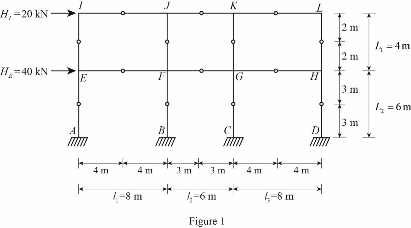
Insert the internal hinges at the midpoints of all the members of the given frame to obtain the simplified frame for approximate analysis.
Draw the simplified frame as in Figure (1).
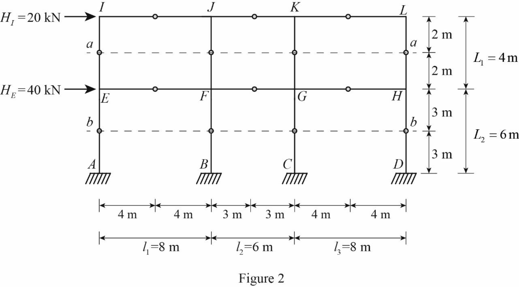
For the calculation of column axial forces of story of the frame, pass an imaginary section aa through the internal hinges at the midheights of columns EI, FJ, GK, and HL, and pass an imaginary section bb through the internal hinges at the midheights of columns AE, BF, CG, and DH.
Draw the free body diagram of the frame portion with the passed imaginary lines as in Figure (2).
Column axial forces:
Above section aa:
Draw the free body diagram of the frame portion above the section aa as in Figure (3).

Refer Figure 3.
Determine the location of the centroid using the relation.
Substitute 0 m for
The given lateral load is acting on the frame to the right, therefore the axial force in column EI and FJ located to the left of the centroid, must be tensile, whereas the axial force in column HL and GK placed to the right of the centroid, must be compressive.
Consider the axial forces in the columns are to be linearly proportional to their distances from centroid.
Apply similar triangle rule.
Determine the relationship in column axial force between the member EI and FJ using the relation.
Substitute 11 m for
Determine the relationship in column axial force between the member EI and GK using the relation.
Substitute 8 m for
Determine the axial force in the column members EI, FJ, GK, and HL using equilibrium conditions.
Take moment about point M.
Substitute
Determine the axial force in the column members FJ.
Substitute 1.69 kN for
Determine the axial force in the column members GK.
Substitute 1.69 kN for
Determine the axial force in the column members HL.
Substitute 1.69 kN for
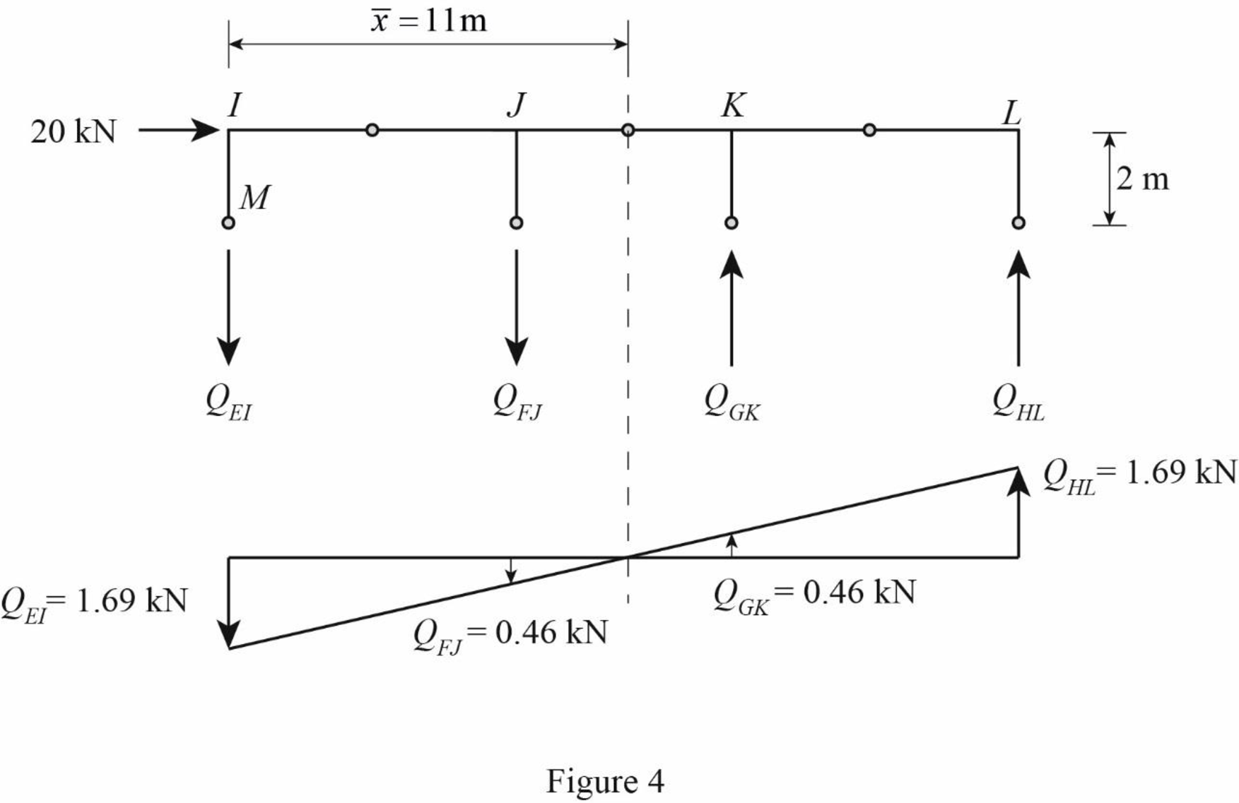
Draw the free body diagram of the frame portion above the section aa with the axial forces in the column members as in Figure (4).
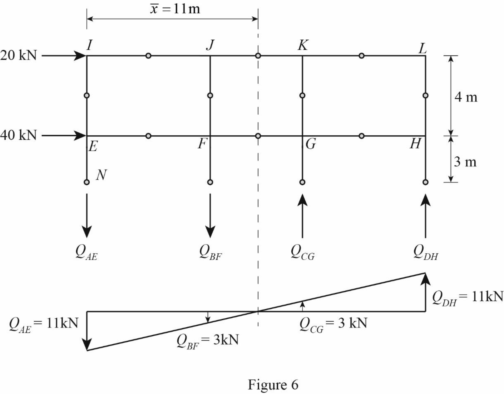
Draw the free body diagram of the frame portion above the section bb as in Figure (5).
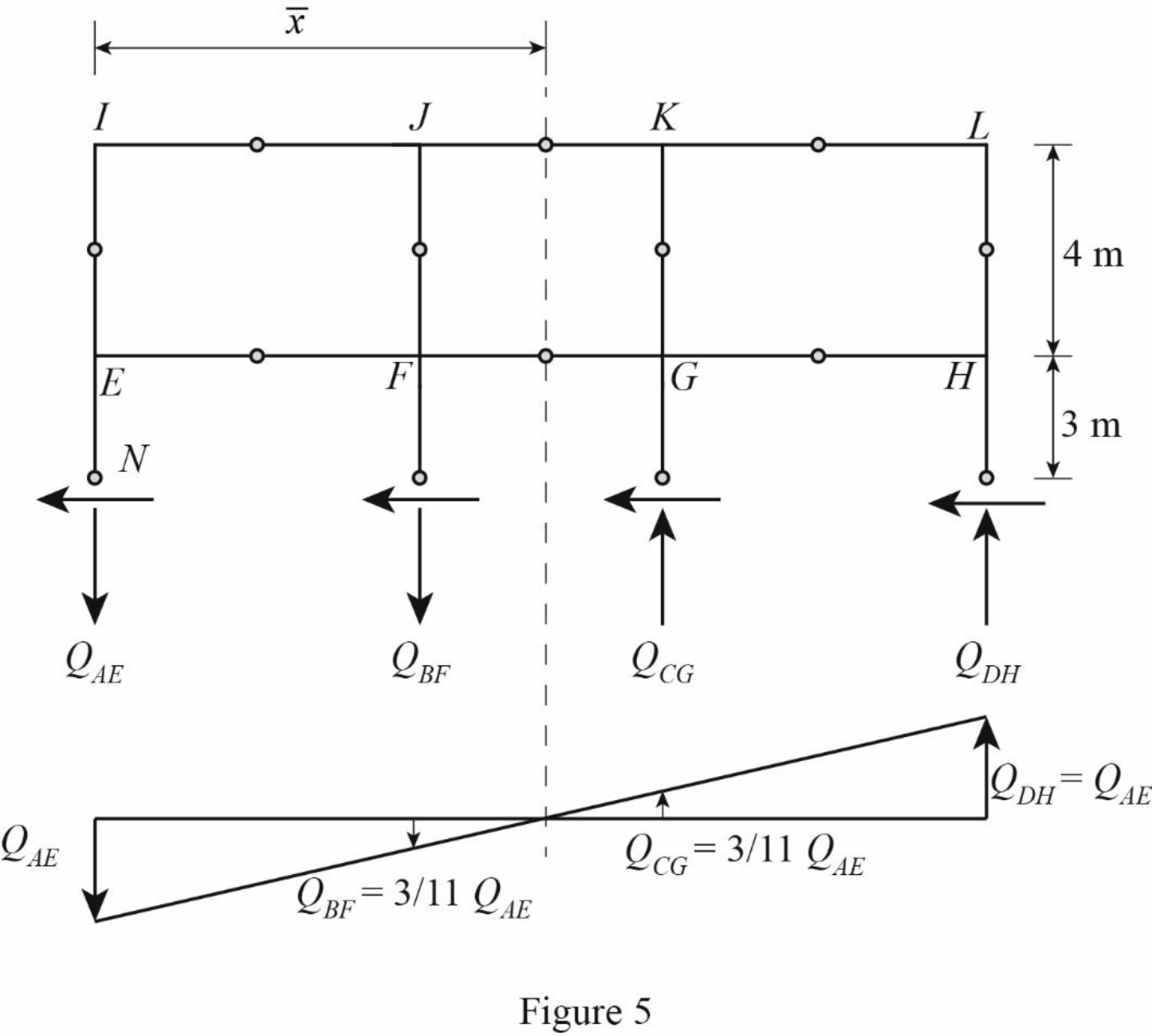
The given lateral load is acting on the frame to the right, therefore the axial force in column AE and BF located to the left of the centroid, must be tensile, whereas the axial force in column CG and DH placed to the right of the centroid, must be compressive.
Determine the relationship in column axial force between the member AE and BF using the relation.
Substitute 11 m for
Determine the relationship in column axial force between the member AE and CG using the relation.
Substitute 8 m for
Determine the axial force in the column members AE, BF, CG, and DH using equilibrium conditions.
Take moment about point N.
Substitute
Determine the axial force in the column members BF.
Substitute 11 kN for
Determine the axial force in the column members CG.
Substitute 11 kN for
Determine the axial force in the column members DH.
Substitute 11 kN for
Draw the free body diagram of the frame portion above the section bb with the axial forces in the column members as in Figure (6).
Girder shear and moments:
Consider girder IJ.
Determine the shear at upper left end joint I using equilibrium equation.
Substitute 1.69 kN for
Determine the shear at upper right end joint J using equilibrium equation.
Substitute 1.69 kN for
Determine the moment at left end of the girder IJ using equilibrium equations.
Substitute 1.69 kN for
Determine the moment at right end of the girder GH using equilibrium equations.
Take moment about point I.
Substitute
Consider girder JK.
Determine the shear at left end joint J using equilibrium equation.
Substitute 1.69 kN for
Determine the shear at right end joint K using equilibrium equation.
Substitute 2.15 kN for
Determine the moment at left end of the girder JK using equilibrium equations.
Substitute 2.15 kN for
Determine the moment at right end of the girder JK using equilibrium equations.
Take moment about point J.
Substitute
Consider girder KL.
Determine the shear at left end joint K using equilibrium equation.
Substitute 2.15 kN for
Determine the shear at right end joint L using equilibrium equation.
Substitute 1.69 kN for
Determine the moment at left end of the girder KL using equilibrium equations.
Substitute 1.69 kN for
Determine the moment at right end of the girder JK using equilibrium equations.
Take moment about point K.
Substitute
Consider girder EF.
Determine the shear at left end joint E using equilibrium equation.
Substitute 1.69 kN for
Determine the shear at right end joint F using equilibrium equation.
Substitute 9.31 kN for
Determine the moment at left end of the girder EF using equilibrium equations.
Substitute 9.31 kN for
Determine the moment at right end of the girder EF using equilibrium equations.
Take moment about point E.
Substitute
Consider girder FG.
Determine the shear at left end joint F using equilibrium equation.
Substitute 9.31 kN for
Determine the shear at right end joint G using equilibrium equation.
Substitute 11.85 kN for
Determine the moment at left end of the girder FG using equilibrium equations.
Substitute 11.85 kN for
Determine the moment at right end of the girder FG using equilibrium equations.
Take moment about point F.
Substitute
Consider girder GH.
Determine the shear at left end joint G using equilibrium equation.
Substitute 11.85 kN for
Determine the shear at right end joint H using equilibrium equation.
Substitute 9.31 kN for
Determine the moment at left end of the girder GH using equilibrium equations.
Substitute 9.31 kN for
Determine the moment at right end of the girder GH using equilibrium equations.
Take moment about point G.
Substitute
Column moments and shears:
Column moment for member EI, FJ, GK, and HL:
Determine the moment at the column member EI using moment equilibrium of joints.
Apply the moment equilibrium of joints at I.
Substitute
The moment at the column member EI is
Determine the moment at the column member FJ.
Apply the moment equilibrium of joints at J.
Substitute
The moment at the column member FJ is
Determine the moment at the column member GK.
Apply the moment equilibrium of joints at K.
Substitute
The moment at the column member GK is
Determine the moment at the column member HL using moment equilibrium of joints.
Apply the moment equilibrium of joints at L.
Substitute
The moment at the column member HL is
Column shear for member EI, FJ, GK, and HL:
Determine the shear at the end I in the column member EI using the relation.
Substitute
The shear at the column member EI must act towards right, so that it can produce Clockwise moment to balance the counterclockwise moment at joint I.
Determine the shear at the end of the column E using equilibrium conditions.
Substitute 3.38 kN for
Determine the shear at the end J in the column member FJ using the relation.
Substitute
The shear at the column member JF must act towards right, so that it can produce Clockwise moment to balance the counterclockwise moment at joint J.
Determine the shear at the end of the column F using equilibrium conditions.
Substitute 6.61 kN for
Determine the shear at the end K in the column member GK using the relation.
Substitute
The shear at the column member KG must act towards right, so that it can produce Clockwise moment to balance the counterclockwise moment at joint K.
Determine the shear at the end of the column G using equilibrium conditions.
Substitute 6.61 kN for
Determine the shear at the end L in the column member HL using the relation.
Substitute
The shear at the column member LH must act towards right, so that it can produce Clockwise moment to balance the counterclockwise moment at joint L.
Determine the shear at the end of the column H using equilibrium conditions.
Substitute 3.38 kN for
Column moment for member AE, BF, CG, and DH:
Determine the moment at the column member AE using moment equilibrium of joints.
Apply the moment equilibrium of joints at E.
Substitute
The moment at the column member AE is
Determine the moment at the column member BF.
Apply the moment equilibrium of joints at F.
Substitute
The moment at the column member BF is
Determine the moment at the column member CG using moment equilibrium of joints.
Apply the moment equilibrium of joints at C.
Substitute
The moment at the column member CG is
Determine the moment at the column member DH using moment equilibrium of joints.
Apply the moment equilibrium of joints at H.
Substitute
The moment at the column member DH is
Column shear for member AE, BF, CG, and DH:
Determine the shear at the end E in the column member AE using the relation.
Substitute
The shear at the column member EA must act towards right, so that it can produce Clockwise moment to balance the counterclockwise moment at joint E.
Determine the shear at the lower end of the column A using equilibrium conditions.
Substitute 10.16 kN for
Determine the shear at the end F in the column member BF using the relation.
Substitute
The shear at the column memer FB must act towards right, so that it can produce Clockwise moment to balance the counterclockwise moment at joint F.
Determine the shear at the lower end of the column B using equilibrium conditions.
Substitute 19.86 kN for
Determine the shear at the end G in the column member CG using the relation.
Substitute
The shear at the column member GC must act towards right, so that it can produce counterclockwise moment to balance the clockwise moment at joint G.
Determine the shear at the lower end of the column C using equilibrium conditions.
Substitute 19.86 kN for
Determine the shear at the end H in the column member DH using the relation.
Substitute
The shear at the column member HD must act towards right, so that it can produce Clockwise moment to balance the counterclockwise moment at joint H.
Determine the shear at the lower end of the column A using equilibrium conditions.
Substitute 10.16 kN for
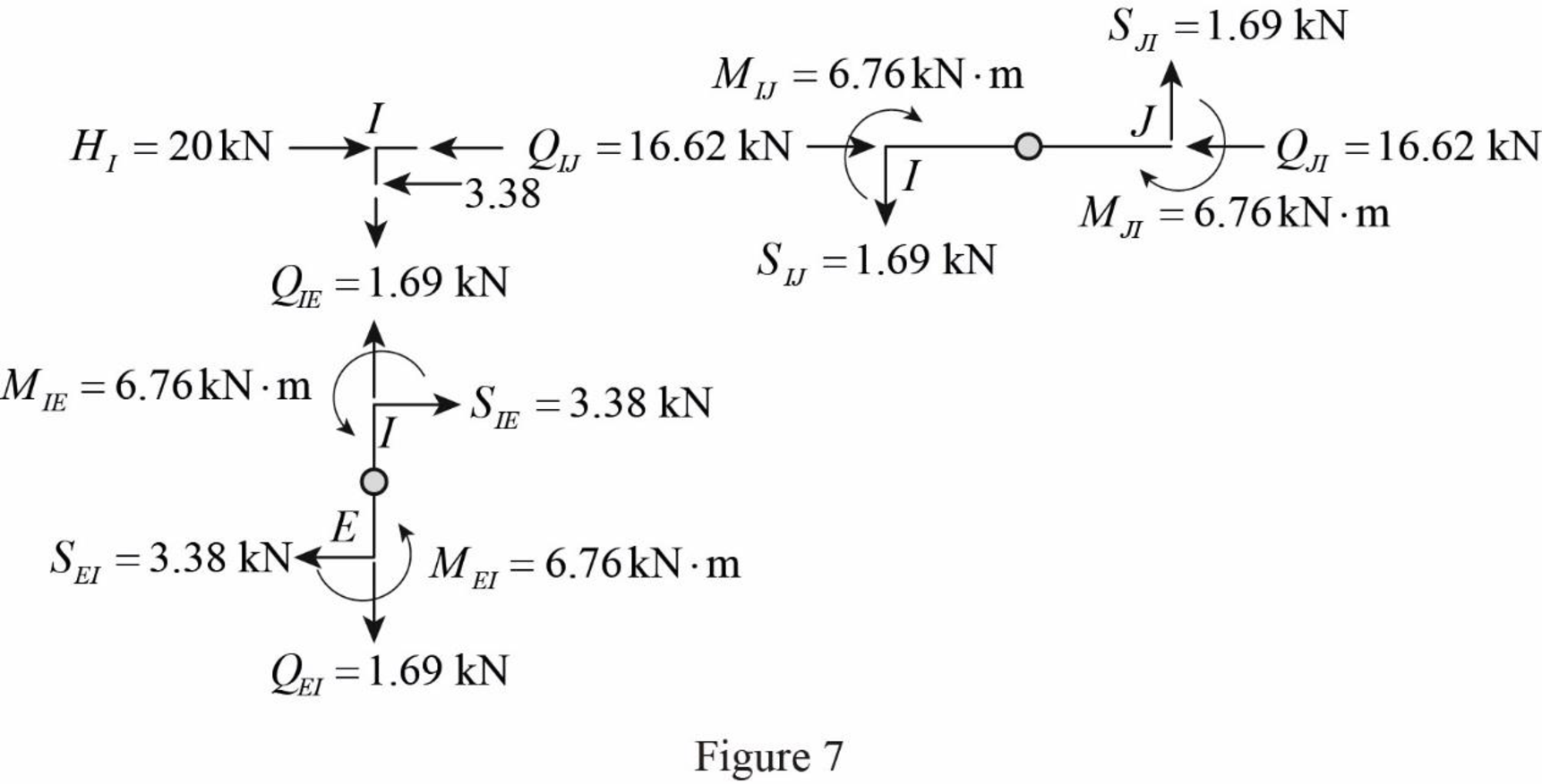
Draw the free body diagram of frame with the column moments and shears for the portion EIJ as in Figure (7).
Girder axial forces:
Girder IJ.
Determine the girder end action at the upper left end joint I using the equilibrium condition.
Apply equilibrium condition at left end joint I.
Substitute3.38 kN for
The girder end action at joint I in the girder IJ is
Determine the girder end action at the upper right end joint H using the equilibrium condition.
Apply equilibrium condition at end joint J.
Substitute 16.62 kN for
Girder JK.
Determine the girder end action at the left end joint J for the girder JK using the relation.
Substitute 16.62 kN for
Determine the girder end action at the right end joint K.
Substitute 10.01 kN for
Girder KL.
Determine the girder end action at the left end joint K for the girder KL using the relation.
Substitute 10.01 kN for
Determine the girder end action at the right end joint L.
Substitute 3.4 kN for
Girder EF.
Apply equilibrium condition at left end joint E.
Substitute 10.16 kN for
The girder end action at joint E in the girder EF is
Determine the girder end action at the right end joint F using the equilibrium condition.
Apply equilibrium condition at left end joint F.
Substitute 33.22 kN for
Determine the girder end action at the left end joint F for the girder FG using equilibrium condition.
Substitute 33.22 kN for
Determine the girder end action at the right end joint G.
Substitute 19.97 kN for
Determine the girder end action at the left end joint G for the girder GH using equilibrium condition.
Substitute 19.97 kN for
Determine the girder end action at the right end joint H.
Substitute 6.72 kN for
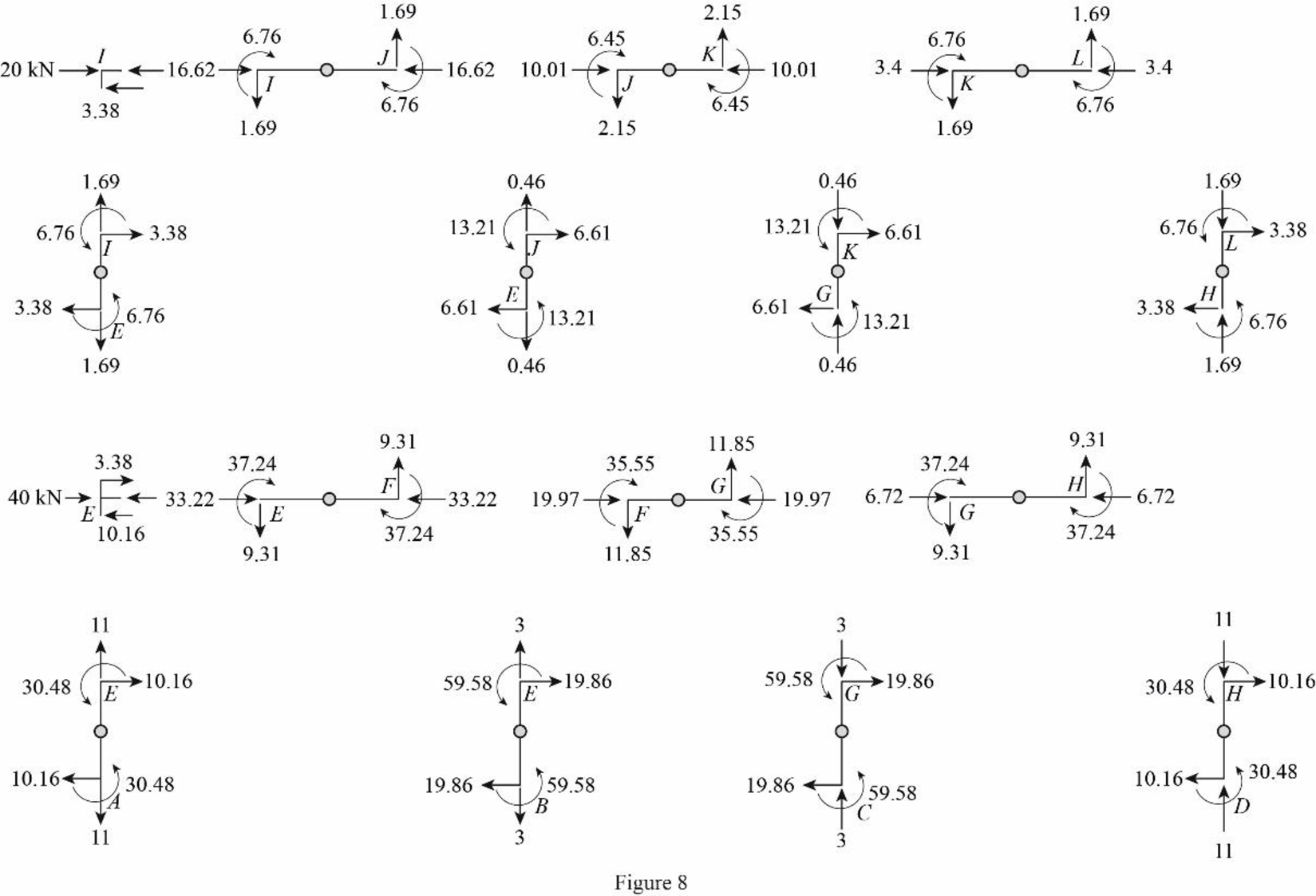
Draw the freebody diagram of the member end forces and moments as in Figure (8).
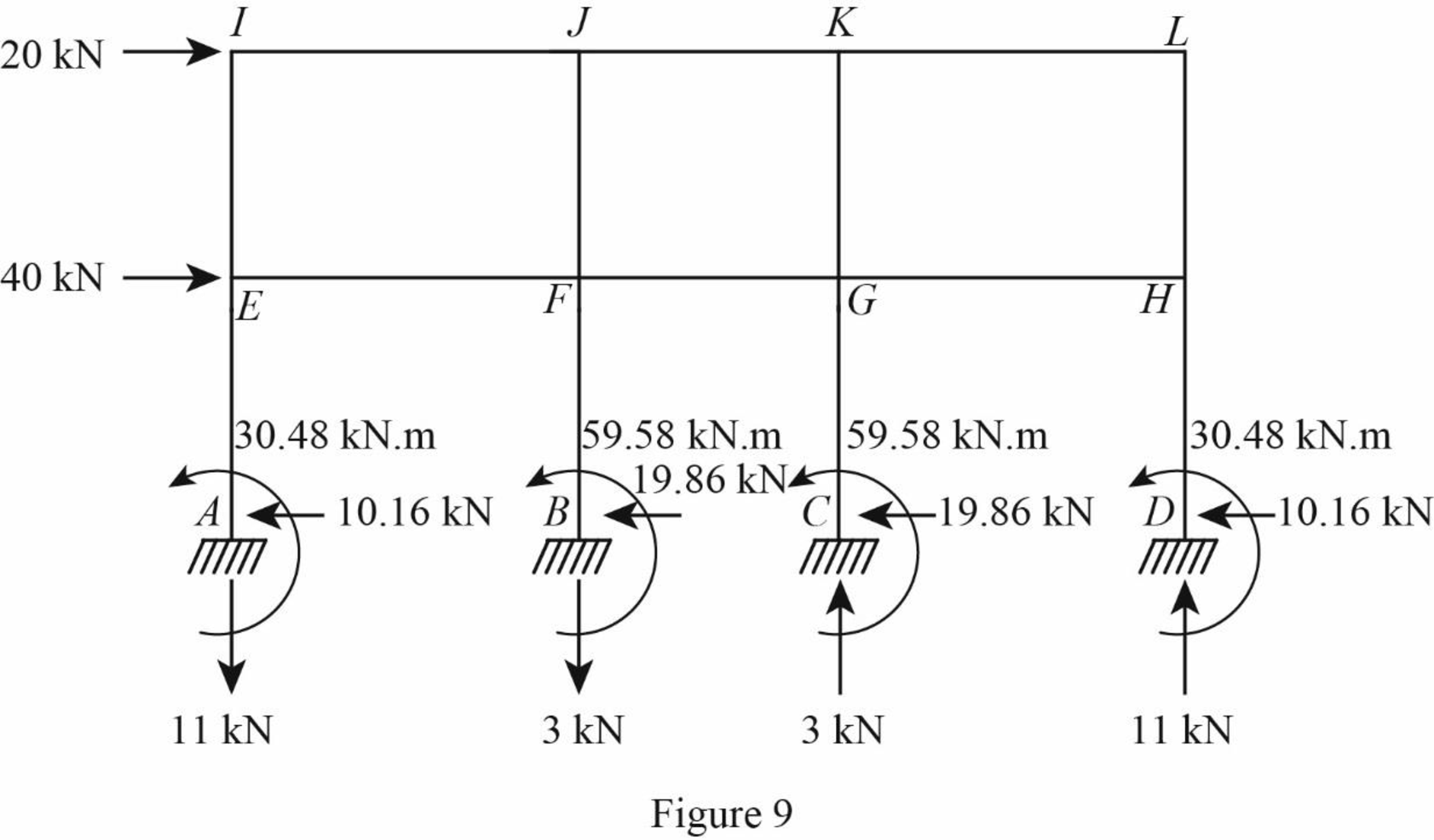
Draw the freebody diagram of the frame with support reactions as in Figure (9).
Want to see more full solutions like this?
Chapter 12 Solutions
Structural Analysis, SI Edition

- Calculate ALL nodal displacements and ALL the member forces in the truss. Please use the ID's noted in the truss diagramarrow_forwardQ3. In a water flood operation in reservoir A, water is being distributed to severalinjection wells from a common injection system; that is, water is supplied to all thewells at approximately the same well head pressure. Routine measurement of theindividual well injection rates by the team of field operators showed that one well wasreceiving approximately 45% more than its neighbours. The sum of the kh productsfor all of the injection wells were approximately the same depth. As a member of theteam, explain:What are the possible causes of the abnormally high injection rate in this well, andwhat production logs or other tests might be run to further diagnose the problem andplan remedial action?arrow_forwardQuestion 1 20 pts Test data on the bending strength of construction wood poles of various diameter are presented below assuming the same length. Kip- 1000 lbf. Using the following data with 2nd order Newton polynomial interpolation, we want to determine the strength of the material for x=4.5 in. Which data point will be used as x? After you found x0, enter the value of x-xo in the solution. Answer shall be in one decimal place. Distance (in) 2.6 1.5 8.3 2.8 5.7 Strength (kips) 100 200 300 400 500arrow_forward
- Solve pleasearrow_forwardsolve all of the last names from A-K to please for example use k=100k/in , m =1000lb/g . use el centro (2nd picture ) to solve the questions. Thank you for your help! for the following questions ignore that last name and just solve it pleae: Verify the modes that are orthogonal Normalize the first mode uisng electro with 2%damping, Determine Sa&Sd only for the first modearrow_forwardFor question 2 do 2% please. Use El centro spectrum to answer the secon question please. Thank you for your help!arrow_forward
- solve pleasearrow_forwardA mechanism for pushing small boxes from an assembly line onto a conveyor belt is shown with arm OD and crank CB in their vertical positions. For the configuration shown, crank CB has a constant clockwise angular velocity of 0.6π rad/s. Determine the acceleration QE of E (positive if to the right, negative if down). 450 mm 215 mm 565 mm A 185 mm 105 mm 110185. mm mm Answer: a = i B 40 mm E m/s²arrow_forwardPlease answer the following questions in the picture, use the second picture to answer some of the questions. I appreciate your help! Explain step by step, thank you!arrow_forward
- Question 5. Three pipes A, B, and C are interconnected as in Fig. 2. The pipe characteristics are given below. Find the rate at which water will flow in each pipe. Find also the pressure at point P. (Neglect minor losses) Pipe D (in) L (ft) f A 6 2000 0.020 B 4 1600 0.032 C 8 3000 0.02 -El. 200 ft P -El. 120 ft B Fig. 2 -El. 50 ft.arrow_forwardcalculate all nodal displacementts and all the member forces of the trussarrow_forwardNOTE: Use areal methods only for V,M,N diagrams(Do NOT use the equations) (also draw the N diagram(s) for the entire structure)arrow_forward
